


Civil Engineers' Blog
Month: January 2016


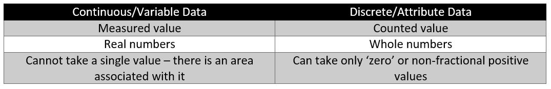
(a) The units and methods of measurement for repair works shall generally be the same as those employed for the construction of the item of work.

Point wiring shall be classified according to the length of wiring as
|
Short points |
Not exceeding 3 m in length |
|
Medium points |
3 to 6 m in length |
|
Long points |
6 to 10 m in length |
|
Special Points |
Length exceeding 10m |
(a) The length of wiring from the main switch board to the sub-main board shall be considered as circuit wiring and shall be measured separately in running metre stating the type and size of wire.
(a) Service connection shall be fully described stating the type and size of the wire and shall be measured as follows
|
Insulated cables |
In running metre |
|
Bare cables |
In kg or quintal |
(b) All over-head bare wire or cables shall be measured in kg of the actual length fixed.
(c) Pole and struts for over-head links shall be enumerated and described stating the type, sectional size, girth or diameter and the total length.
(d) Steel brackets, cross-arms, clamps, etc., fixed to poles and struts shall be fully described and enumerated under separate item.
(e) Stay assemblies shall be enumerated and fully described including excavation, concrete, etc.
(f) Earthing poles and service connections shall be enumerated and fully described as including earth electrode, packing charcoal, earth wire, etc.

(a) Gullies, syphons, intercepting traps, etc., including concrete bedding and setting in position shall be enumerated stating the size.
(b) Connection of fittings, elbows, bends, tees, connectors, unions, diminishing sockets and the like shall be enumerated.
(c) Cutting through walls, floors, etc., and making good shall be included with the item.
(d) Closet pans, urinals, flushing cisterns, lavatory basins, bath tubs, shower rose and other fittings shall be enumerated stating the size and fully described.
(e) Sluice valves, stop cocks, hydrants, surface boxes, water meters, etc., shall be described stating size and enumerated.
(f) Bib-cocks, pillar cocks, ball cocks, ferrules, grating, etc., shall be described stating the size and enumerated.
(g) Boilers, cisterns, cylinders, water tanks, etc., shall be enumerated stating the size, capacity, materials, etc., and fully described.
(a) Manholes up to 6m depth shall be enumerated stating the size and depth and shall include cast iron cover with frame (weight to be stated), foot iron, inverts, materials and mortar, framework, etc., all of which shall be fully described.
(b) Manholes shall be classified under three different groups as follows: –
|
Shallow |
Up to 2.1m in depth |
|
Deep |
Above 2.1m and up to 4.2m in depth |
| Extra Deep |
Above 4.2m and up to 6.0m in depth |
(c) Manholes under each classification shall be enumerated separately stating the size and least depth and the extra depth shall be measured in running metre and totaled up separately for each classification and taken as ‘extra over’ under separate item following the main item.
(d) Depth shall be from the top of manhole to the invert of channel.
(e) Manholes exceeding 6 m in depth shall be measured in details under the various items of works, brickworks, concrete, C.I. cover with frame, etc.

(a) Painting of door and window shall be measured closed and flat, not girthed in sq.m. and shall include chaukhats, edges, cleats, etc.
(b) Different types of doors and windows as battened, paneled, glazed, etc., shall be grouped under one item and the areas of uneven surfaces shall be covered into equivalent plain area by multiplying the flat measured area by a multiplying factor.
(c) The coefficients or multiplying factors for different surfaces to get equivalent plain area are as given below: –
|
Particulars |
Method of Measurement |
Multiplying Factor |
|
Doors and windows |
||
| 1. Paneled, framed, and braced, ledged and battened, ledged battened and braced. | Measured flat not girthed including chaukhats, edges chocks, cleats, etc., shall be included in the item. | 1 1/8 (for each side) |
| 2. Fully glazed or gauged | Same as above | ½ (for each side) |
| 3. Part paneled and part glazed or gauged | Same as above | 1 (for each side) |
| 4. Flush door | Same as above | 1 (for each side) |
| 5. Flush venetioned or louvered | Same as above | 1 ½ (for each side) |
|
Miscellaneous works |
||
| 6. Boarding with cover fillets and match boarding | Measured flat not girthed | 1 1/20 (for each side) |
| 7. Roof battens (tile or slate roof) | Measured flat overall, no deduction for open spaces | ¾ (for painting all over) |
| 8. Trallies or jaffri work one way or two way | Same as for (6) above. (Supporting members shall not be measured separately) | 2 (for painting all over) |
| 9. Guard bars, balustrates, grating, railings, grills, expanded metals, etc. | Measured flat overall no deduction for open spaces | 1 (for painting all over) |
| 10. Corrugated iron sheeting in roof | Measured flat not girthed | 1.14 (for each side) |
| 11. A.C. corrugated sheeting in roof | Measured flat not girthed | 1.20 (for each side) |
| 12. A.C. semi corrugated sheeting in roof | Measured flat not girthed | 1.10 (for each side) |
| 13. Steel rolling shutters | Measured flat not girthed | 1 ¼ (for each side) |

| Corrugated iron sheet | 14% |
| Corrugated asbestos cement sheet with large corrugations (as Big six sheets) | 20% |
| Semi – corrugated asbestos cement sheets (as Trafford sheets) | 10% |


(a) Structural steel works as girders, compound girders, plate and lattice girders, steel stanchions, trusses, framed steel work, etc., shall each be taken under separate item and measured in quintal and fully described.
(b) No deduction shall be made for rivet and bolt holes.
(c) In riveted work, the weight of rivet heads, except in case of countersunk rivets, shall be added.
(d) The weights of cleats, brackets, packing pieces, separators, gusset and fish plates, bolts and nuts, rivet heads, etc., shall be added to the weight of the respective items.
(e) The work shall include fabrication, hoisting, placing, fixing in position.
(f) Site drilling to existing steel work shall be enumerated stating the diameter of bolts and thickness of metal.
(g) Rivets driven at site shall be enumerated as ‘extra over’.
(a) Bolts, holding down bolts, anchor bolts, etc. shall be measured in quintal separately including nuts and head, and washers shall be grouped according to the diameter.
(b) Grills grating, framed guard bars, ladders, brackets, etc., shall be measured in quintals separately and shall be fully described.
(c) If specified grills, grating, etc., may be taken in sq.m. and fully described.
(d) Iron hold fasts shall be taken by weight in quintal, or enumerated stating the length, breadth and thickness of flat iron.
(e) The method of fixing with bolt of screw and embedding in cement concrete or cement mortar shall be described and included in the item.
(f) Flue pipes shall be measured in running metre stating the diameter and the type of pipe, gauge or weight per unit length and method of jointing and fixing shall be described.
(g) Cast iron balusters and newels shall be enumerated and fully described including the methods of fixing.
(h) Cast iron railings shall be measured in running metre stating the height and fully described including the method of fixing.
(a) Cast iron spiral staircase shall be enumerated (i.e., counted as one for complete work) stating the overall diameter, total number of treads and total height above ground level.
(b) The description shall include tread, riser and sleeves in one piece, including hand rails, balusters, etc.
(c) Cast iron chequered plates shall be described and measured in quintal.
(d) Expanded metal, wire netting, etc., shall be measured in sq.m. stating gauge and mesh.
(e) No deduction shall be made for opening up to 0.2 sq.m.
(f) Different items shall be kept separate.
(a) Bar reinforcement shall be measured by weight in quintal stating the diameter and shall include cutting to length, hooked ends, cranking or bending, etc.
(b) Authorized overlaps shall be measured.
(c) Different diameter bars shall be kept separate.
(d) Binding wire shall not be measured separately, this shall be included in the item.
(e) Fabric reinforcement shall be taken in sq.m. stating the mesh and size of standard.
(f) Wire netting in wrappings to steel work embedded in concrete or plaster, in encasing steel work shall be measured separately in sq.m. stating the mesh and gauge.
(g) Hoop iron shall be measured in running metre stating the width and gauge.

(a) Generally, all woodwork of which the scantling exceeds 20 sq.cm. in section and which is not specially molded or carved comes under carpenter’s work.
(b) This includes all timber work in door and window chaukhats, in roof works as beams, struts, ties, rafters, purlins, (all work in roof trusses), in timber bridge, in verandah posts, in centering and shuttering, in shoring and the like.
(a) Woodwork which is prepared, turned, molded, carved and jointed together comes under joinery.
(b) Joiner’s work requires finishing and putting together at the bench and includes door and window shutters, framed partitions, furniture and the like.
Carpenter’s work
(a) Roof boarding, ceiling, floor, shelves, partitions, etc., shall be taken in sq.m. stating the finished thickness and shall be fully described.
(b) Supporting beams, frame work, shall be taken separately in cu.m.
(a) Normally, centering and shuttering (formwork) shall not be measured separately but included in the rate of C.C. or R.C.C. work.
(b) If specified that the formwork shall be paid separately, the formwork shall be measured as the actual surface contact with the concrete and taken in sq.m. and shall include planking, beams, props, wedges, nails, etc.
(c) Formwork of different kind of works as beams, lintels, floors, roofs, walls, columns, staircases, etc., shall be measured under separate items and fully described.
(d) For slabs, chujjas, arches, shells and domes only the area of bottom shuttering in contact with concrete surface shall be measured and side shuttering shall not be taken into account.
(a) Roof battens, where not included with the item of roof, shall be taken as surface area of the roof in sq.m. stating the size of battens and the spacing.
(a) Fillets, beadings, etc., shall be measured in running meter stating the width and thickness.
(a) Finishing of fillet as edge chamfered, rounded or molded shall be described.
(a) Ballies shall be measured in running meter stating the mean diameter which shall be average of the two diameters at the ends.
(a) Wood piles shall be measured in running meter stating the size.
(b) Steel shoes and heads of piles shall be enumerated separately stating their weights.
Joinery
(a) Shutter shall be taken in sq.m. stating the thickness and the kind of wood and both faces shall be described.
(b) Measurement shall be taken from inside after closing the shutters excluding chaukhats.
(c) Different types of shutters are:
(d) Ledged and battened,
(e) Ledged, braced and battened,
(f) Framed, ledged braced and battened,
(g) Framed and paneled,
(h) Framed and louvered,
(i) Flush,
(j) Glazed,
(k) Part paneled and part glazed, etc., shall be taken separately and each type fully described.
(a) For supply, glass panes shall be measured in sq.m. stating the thickness and type of glass.
(b) Measurement, length and breadth, shall be taken to the nearest 5 mm.
(c) Irregular or circular panes shall be measured at the smallest rectangular area from which they can be cut unless otherwise specified.
(a) Chaukhats, mullion and transoms shall be taken in cu.m. and the length of tenon, horns, etc., shall be added to the sight lengths.
(b) The sectional area shall be the area of the least square and rectangle from which they may be cut or made.
(c) Rebates, beads, chambers, etc., shall be described and included with the item.
(d) Portion of chaukhats of segmental or circular shape shall be measured separately and described.
(e) Type of wood shall be stated and chaukhats of different kind of wood shall be kept separate.
(a) Work of staircase shall be measured under separate heading.
(b) Landing including bearers shall be measured under a separate item in sq.m. of the upper surface, stating the thickness.
(c) Treads and risers shall be taken in sq.m. stating thickness, the area being obtained by multiplying the length of tread by the exposed width of the tread plus the rise from step to step and the work shall be described stating the kind of timber’s method of jointing, fixing, etc.
(d) Hand rails shall be taken in running meter and measured along the top centre line stating the extreme section of the straight portions and molding and rounding.
(e) Balusters shall be taken in numbers stating the size and shall include framing, at ends shall be fully described.
(f) Newels shall be described and measured in running meters stating the section and nature of finishing.
(a) Towel rails, contain brackets, plate racks, toilet fixtures, small fittings, furniture, etc., shall be taken in numbers stating the size and shall be fully described.
(a) Builder’s hardware is the trade name of the articles made of base metal as iron, steel, copper, etc.
(b) The various kinds of builder’s hardware shall be described and enumerated and taken separately according to the materials, finish, size and pattern.
(c) The following articles comes under builder’s hardware: –
-Hinges, door handles, hasp and staples, locks, hat pegs, hat and coat hooks, wardrobe hooks, knobs, springs, screwed eyes, cleats, latches, bolts and the like.
-Curtain rods or poles, curtain rails, rails for running sashes, etc., shall be measured in running meter stating diameter and size.
(a) Glazing shall be measured in sq.m. stating the quality, weight and thickness.
(b) The method of glazing and fixing with putty, wooden beads, metal beads, etc., shall be fully described.
(c) Different kind of glass and different methods of fixing each shall be taken separately.

The stone masonry in uncoursed rubble or coursed rubble, etc. shall be measured separately in cubic metres. Usually stone masonry in foundation and up to plinth (if of the same type) is included under one item and the masonry in superstructure is considered as separate item. For multi-storeyed buildings, the masonry at each floors is to be measured separately.
The procedure of calculating the net quantity of stone masonry is to assume all walls as solid and to calculate its cubic contents, and then deductions are to be made for the various openings such as doors, windows, ventilators, etc.
The rules of deduction for the openings in stone masonry are same as for openings in the brick work already explained in the topic ‘Brick Work’
The stone work for sill and parapet copings are measured in running meters, specifying the item fully in the description column.
The face stone work for weather sheds, shelves, slabs, etc. are measured in square metre.

(a) Brick walls up to and including three bricks in thickness shall be measured in multiples of half brick, which shall be deemed to be inclusive of the mortar joint.
(b) The following shall be taken as half brick measurement: –
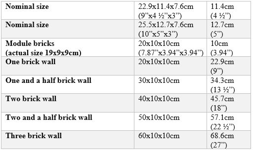
(c) For walls which are more than three brick in thickness, the actual thickness shall be measured to the nearest 1 cm (½”).
(d) Where fractions of half brick occur due to architectural or other reasons, the measurements shall be taken as follows: –
-For fractions of 2 cm under actual measurement.
-For fraction exceeding 2 cm – full half brick.
(a) No deduction or addition shall be made for the following: –
-Opening up to 0.1 sq.m. in section.
-Ends of joints, beams, lintels, posts, rafters, purlins, corbels, steps, etc.
-Wall plates and bed plates, bearing of slabs, chujjas and the like where the thickness does not exceed 10 cm and the bearing does not extend over the full width (thickness) of wall.
The size of the bricks, its type, thickness of the joints, bond, etc., and the proportion of mortar shall be specified in the description of the item.
The main brick work is measured in cubic metres, and brick work in partition i.e., one brick thickness is measured in square meter specifying its thickness. Brick masonry in foundation and up to plinth is included under one item and the brickwork in superstructure is measured separately. In case of multi-storeyed building, the brick work of each floor is to be measured separately as the rates of the item go on increasing from ground floor to subsequent higher floors.
The general procedure of calculating the quantities of brick work in superstructure is to assume all walls as solid and find out its cubic contents, and then allow for the deductions for openings into it. Example: doors, windows, ventilators, lintels, etc. Different types of brick work with different proportion of mortar, etc. shall be measured separately.
Honey combed brick work is measured separately, specifying the thickness in square metres, no deductions being made for the holes in it.
Rules for deductions to be made for openings in brick wall are as follows:
Thus the quantity of deduction to be made shall be equal to:
(l + 2t) x (Thickness of lintel) x (Wall thickness)
where t = Thickness of lintel and l = Length of the opening.
It may be noted that lintels also from separate item to be measured in cubic metres. the quantity being equal to = (l + 2t) x t x Wall thickness
Brick work in columns and pillars shall be described fully and shall be measured separately in cubic metres.
Circular brick work above 6 m radius shall be measured in the general item of brick work in cubic metres.
Brick work in staircase, arches, etc. shall be measured separately in cubic metres.

(a) Reinforced cement concrete shall be kept separate from unreinforced concrete,
(b) C.C. work shall be taken in cu.m. excluding steel, and the steel reinforcement shall be measured under a separate item in quintal (cwt), authorized overlap hooks, cranks, etc. of bars shall be measured.
(c) Normally, centering and shuttering (formwork) shall not be measured separately but included in the rate of R.C.C. or C.C. work.
(d) Binding wire is not measured separately.
(e) The volume occupied by reinforcement shall not be deducted from the measured concrete volume.
(f) The item of R.C.C. work shall include R.C.C. slabs, beams, lintels, columns, chujjas, staircases, foundation, rafts and footings, etc. and each of them shall be classified under a separate item.
(g) The exposed surface shall be fair finished which shall not be measured separately.
(h) Chujjas may be measured in running meter stating the projection and its average thickness, if specified.
(i) Special light weight partitions shall be measured in sq.m. stating thickness and fully described.
Precast C.C. reinforced or plain shall be taken separately in cu.m. and shall be described as including all molds, finished faces hoisting and setting in position.
Reinforcement, if any, shall be described and included in the item, or measured separate if specified.
(a) Expansion joints in roofs, floors, walls, road, etc. shall be measured in running meter.
(b) The depth and width of joint, and materials used for filling shall be described.
(a) Jallies or Jafferies, louvers shall be described and thickness specified and taken in sq.m.
(b) Reinforcement shall be described and included in the item.
(a) Fencing posts, corner posts, struts, etc., shall be taken in cu.m. and reinforcement and formwork shall be included and described.
(a) Concrete piles shall be described and taken in cu.m. and classified according to the section and length.
(b) Steel reinforcement shall be included with the item and fully described.
(c) Heads and shoes of steel or iron shall be enumerated i.e., taken in numbers and weight of each stated.
(d) Pitching and driving of piles shall be enumerated stating size and length.
If specified, the driving of piles may be taken and measured in running metre for the portion driven below ground level.
(a) Damp proof course shall be fully described and taken in sq.m. stating the thickness.
(b) The item shall include formwork, finishing, levelling, curing, etc.
(c) The horizontal and vertical damp proof courses shall be measured separately.
It may be plain cement or reinforced cement concrete:
(a) Plain Cement Concrete (P.C.C.):

(b) Reinforced Cement Concrete (R.C.C.):
i) Columns: The length or height of the column shall be measured from top of the footing on which column rests to the underside of the first slab for the ground floor and the top of the floor slab to the underside of the floor slab immediately above it. (see Fig. 3.6)
ii) Beams: The length of the beam shall be measured clearly between the two columns and shall be inclusive of haunches between columns and beams, if any. (See Fig. 3.7) 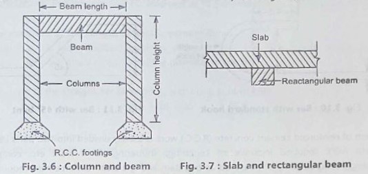
The depth of the ordinary beam shall be measured from the bottom of the beam to the bottom of the slab above it. In case of inverted beams, however, it is measured from top of the slab to the bottom of the beam.
iii) Slab: The depth of the slab shall be measured from the top of the slab to the top of the rectangular beam lying below it. (See Fig 3.7) In case of slab and T or L-beam, the common portion shall be measured in the T-beam.
iv) In case of concrete chajjas combined with lintels or beam, the common portion shall be included into lintel only. (See Fig. 3.9)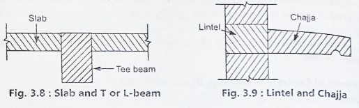
The common portion at the junction of two similar members is usually included with only one item.
Example: In case of junction of column and beam, the common portion of the work is included in the column (See Fig. 3.6), and in case of slab and rectangular beam, the common portion is included in the slab (See Fig. 3.7), whereas in case of slab and T-beams (or L-beams), the common portion is to be included in the T (or L) beam. (See Fig. 3.8) and in case of lintel and chajja the portion common to it is measured in the lintel. (See Fig. 3.9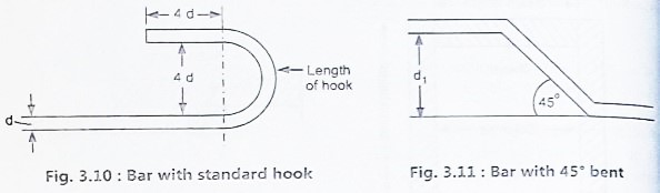
The item of reinforced cement concrete (R.C.C.) work is usually divided into two parts i.e., the concrete work required inclusive of centering, shuttering, form work, etc. completely (excluding reinforcement) is measured as one item and the steel reinforcement required is considered as another separate item, no deductions being made for the space occupied by the steel from the volume of concrete. Binding wire required is to be included in this item and separate measurements are required for it.
The quantity of concrete work in R.C.C. is calculated in cubic metres knowing the length, width, and depth of the concrete. The quantity of reinforcement steel to be laid in position is also worked out from the details shown on the drawings, making due allowance for overlaps, hooks and cranks, etc. In the absence of such detailed reinforcement drawings, the quantity of reinforcement steel may be worked out approximately on the percentage of the volume of concrete as specified below:
For foundation footings = About 0.5% of volume of concrete
For column = About 1.2 to 2.5% of volume of concrete
For beam = About 1 to 1.5% of volume of concrete
For slab and lintels = About 0.8 to 0.9% of volume of concrete
A thin rich cement plaster may be applied to the exposed R.C.C. surfaces to give uniform smooth finished surface, without making separate item. No deduction shall be made for the volume of the reinforcing bar from the volume of concrete.
Consider a bar with standard hook as shown in Fig. 3.10. The length of the hook = d + 4d+ 4d = 9d, where d represents the diameter of the bar.
Length of the straight bar of length L, with hook at both ends = L + 9d +9d = L + 18d
For a 45 degree bent up bar (Fig. 3.11),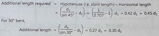
For 60 degree bent,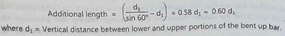
It is usual practice to prepare a schedule of reinforcement bars which will be useful for bar bender and supervisors, etc. It contains of a list of reinforcement bars specified in a tabular form, indicating its diameter, shape of bending with neat sketches, length of each angle of bent, its total weight, etc. Such a schedule of bars is prepared separately for each type of R.C.C. work such as slabs, beams, columns, etc. From the schedule of bars, it is possible to determine the total requirement of reinforcement for that item of work with its length, diameter, etc. and accordingly the job of bending of bars, etc. as per the drawings can be carried out before it is placed in the position before casting of the member.
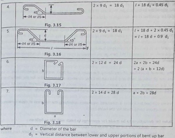
Some of the usual types of reinforcement bars with the length of hooks and the total length of the bar required are as mentioned below:

(a) The measurement shall be taken separately for every 30 m lead or distance and every 1.5 m lift or height or depth.
(b) The lead shall be measured from the centre of the area of excavation to the centre of the area of spoil heap.
(c) Similarly, lift shall be measured from the centre of excavation to the centre of spoil heap.
(d) The normal rate is for each unit of 30 m lead and 1.5 m lift. For grater lead or lift, the rate shall be different for every unit of 30 m lead, and for every unit of 1.5 m lift.
(a) Unless otherwise specified, the foundation trench shall be measured in cu.m. for rectangular section, bottom width being width of concrete and the depth shall be measured as vertical depth even though the contractor might have excavated with sloping sides for convenience.
(a) Returning, filling and ramming excavated earth shall be taken in cu.m. under a separate item and shall include spreading in layers of 20 cm in depth, watering, ramming and leveling.
(a) Clay puddle work shall be taken in cu.m. and shall be described including supply of clay, its preparation, placing in layer of 15 cm, ramming, etc.
(a) Trimming and dressing of natural ground to remove vegetation and small irregularities not exceeding 15 cm deep shall be taken in sq.m. under a separate item ‘Surface Dressing’.
(b) Cutting down of trees exceeding 30 cm girth shall be accounted separately and enumerated i.e., taken in numbers, stating the girth at 1 m above ground and paid separately.
(a) Excavation exceeding 1.5 m in width as well as 10 sq.m. in plan but not exceeding 30 cm in depth shall be described as Surface excavation and measured in sq.m.
(a) When spring water requires pumping, the work of pumping and dewatering shall be taken under separate item.
(a) Timbering or ‘Planking and Strutting’ for protecting the sides of trench or loose earth, shall be measured in sq.m. of face supported, and shall be classified under separate items as: –
(b) Depth not exceeding 1.5 m,
(c) Depth exceeding 1.5 m but not exceeding 5 m,
(d) Depth exceeding 5 m.
(e) Timbering shall include all necessary timber work including walls, struts, poling boards, etc.
(f) Both sides of trench shall be taken as one side area and shall be equal to length x depth of timbering.
As per I.S. 1200 of 1974, the measurement of the item of earth work shall be carried out as follows:


(a) The chaukhats shall be properly framed and joined by mortise and tenon joint with hard wood pins, and the joints shall be coated with white lead before being fitted together.
(b) The chaukhats shall be of section as per drawing, may be 7.5 cm x 10 cm, 10 cm x 10 cm, 8 cm x 12 cm or similar section.
(c) Concealed faces of chaukhats shall be painted with two coats of coal tar or solignum and other faces shall be painted with a prime coat before fixing in position.
(a) The shutters should be paneled, glazed, part paneled and part glazed, battened, or venation as specified.
(b) The thickness of shutters shall be 3 cm to 5 cm as specified.
(c) The styles rails and panels shall be planed and neatly and truly finished to the exact dimensions.
(d) The styles and rails shall be framed properly and accurately with mortise and tenon joint and fixed with wooden pins.
(e) Panels shall be of one piece without any joint and shall be fixed with 12 mm insertion into the rails and styles and rails provided with moldings as per design.
(f) The thickness of panels shall be 12 mm to 25 mm as specified.
(g) All rails over 15 cm in width shall have double tenon.
(h) No tenon shall exceed one-fourth of thickness of the plank.
(i) For glazed windows, sash bars shall not be less than 40 mm x 40 mm and glasses shall be fixed with nails and putty or with wooden beadings over felt as specified.
(j) All joints shall be glued before being fitted.
(a) All doors shall be provided with handles on both sides and all windows with handles on the inner side.
(b) One of the door of each room shall be provided with sliding bolts, on the outer side of locking.
(c) Necessary hinges, tower bolts, hook bolt stops for keeping the leaves open, and also wooden blocks to prevent leaves striking the jambs of wall, etc., shall be provided.
(d) The fitting may be of iron, brass of oxidized as specified of approved quality.
(e) Screws shall be suitable length and correct diameter and shall be fixed with screw driver and not by hammering.
(a) The surface of shutters and chaukhats shall be painted with two coats of approved paint over a coat of priming.
(b) Faces of chaukhats in contact with masonry shall be painted with two coats of solignum or coal tar or other preservative before fixing.
(c) A prime coat of painting with primer paint shall be applied on the remaining surfaces before fixing in position.
(a) The rate shall be for the complete work including hanging and fixing in position.
(b) The chaukhats shall be measured in cu.m. under wood work for the finished work, and the length of tenon, horns, etc., shall be added to right lengths.
(c) The measurement of shutters shall be taken in sq.m. for the finished work in closed position, overlaps of two shutters shall not be measured.
(d) The painting shall be measured separately under a separate item in sq.m.
(e) The cost of fitting may be excluded if specified, and the fitting supplied by the department or owner, but the fixing of fitting and hanging in position shall be included in the rate.

(a) Pure shellac varying from pale orange to lemon yellow color, free from resin, dirt, etc., shall be dissolved in methylated spirit at the rate of 0.15 kg of shellac to 1 liter of spirit.
(b) Suitable pigment shall be added to get the required shade.
(a) The surface of the timber shall be cleaned and rubbed down smooth with sand paper.
(b) Knots if visible shall be covered with a preparation of lead and glue size laid on while hot.
(c) Holes and indentations on the surface shall be filled with putty and smoothed.
(d)The surface shall then be given a coat of wood filled made by mixing whiting (powdered chalk) in methylated spirit at the rate of 1.5 kg of whiting per liter of spirit.
(e) The surface shall then be rubbed down perfectly smooth with glass paper and wiped clean.
(a) A pad of woolen cloth covered by fine cloth shall be used to apply the polish.
(b) The pad shall be moistened with the polish and rubbed hard on the wood, in series of overlapping circles applying the polish sparingly but uniformly over the entire surface to give a uniform surface and high gloss.
(c) Number of coat shall be as specified.
(d) The second coat shall be applied, after the first is dried, in the same way as for the first coat.


(a) Oil distemper is similar to ordinary dry distemper in powder form.
(b) In the oil distemper compound (dry powder), oil is mixed by the manufacturer while manufacturing.
(c) For application of oil distemper, it is mixed with the required quantity of water and then applied on the surface.
(d) The methods of preparation and application are similar as described above.


(a) For colored finish, the surface shall be finished with colored cement or with a mixture of ordinary Portland cement and colored pigment of the desired color in the proportion of 3 of cement and one of color (or 4:1 or 5:1).
(b) For colored floor, the thickness of the two layers shall be 19 mm and 6 mm.
(c) For polished floor the thickness of surface cement finishing should be 2.5 mm to allow for grinding and polishing.
(a) In ground floor, the c. c. floor is to be laid on a 7.5 cm base of lime concrete or weak cement concrete as per standard specifications.
(b) If the base consists of cement concrete, it shall be allowed to set for about 7 days.
(c) In case the base is of weak cement concrete, the flooring shall commence within 48 hours of laying the base.
(d) In first floor or upper floor if c. c. floor is to be laid on R.C.C. slab, the surface of R.C.C. slab shall be made rough with brushes while concrete is green.
(e) Before laying the c. c. floor, the surface shall be cleaned, wetted and a neat cement wash shall be applied to get a good bond.
(f) A base of lime concrete may also be provided over the R.C.C. slab if specified.
(g) The base shall be provided with the slope required for the flooring.
(h) The thickness of c. c. bed for office building, school building, and in upper floor should be 4 cm.

(a) The mortar shall be pressed into the raked, cleaned and wet joints and shall be finished off flush and level with edges of brick to give a smooth appearance.
(b) The edges shall be neatly trimmed with a trowel and straight edge.
(a) The mortar shall be pressed into the raked, cleaned and wet joints and a groove of shape and size of 5 to 6 mm deep shall be formed running a forming tool of steel along the centre line of the joint.
(b) The vertical joints also shall be finished in a similar way at right angles to the horizontal lines.
(c) The finished work shall give a neat and clean appearance with straight edges.
(a) The mortar shall be applied on the raked, cleaned and wet joints, and horizontal joints shall be pressed and finished with a pointing tool so that the joint is sloping from top to bottom.
(b) The vertical joint shall be finished as ruled pointing.
(a) The mortar shall be applied in raked, cleaned and wet joints in excess to form raised bands.
(b) The mortar shall be pressed and run with proper tool to form bands of 6 mm raised and 10 mm width as directed.
(a) Cement, sand mortar – 1:3, 1:4, 1:5, 1:6
(b) Cement, lime, sand mortar – 1:1:6; C:L:S
(c) Lime, surkhi or sand mortar – 1:1, 1:2; Kankar lime mortar, Kankar lime alone.
(d) For ceiling plastering 1:3 cement mortar with coarse sand is generally used.
(e) Cement, lime sand mortar is slow setting and has better workability than cement, sand mortar.

(a) All bricks shall be of first class of standard specifications made of good brick earth thoroughly burnt, and shall be of deep cherry red of copper color.
(b) Bricks shall be regular in shape and their edges should be sharp and square and shall emit clear ringing sound on being struck, and shall be free from cracks, chips, flaws and lumps of any kind.
(c) Bricks shall not absorb water more than one-sixth of their weight after one hour of soaking by immersing in water.
(d) Bricks shall have a minimum crushing strength of 105 kg per sq.cm
(a) Mortar shall be specified and materials of mortar shall be of standard specifications.
(b) For cement mortar, cement shall be fresh Portland cement of standard specifications.
(c) Sand shall be sharp, clean and free from organic and foreign matters.
(d) For rich mortar, coarse or medium sand should be used and for weak mortar, local fine sand may be used.
(e) Proportion of cement sand mortar may be 1:3 or 1:6 as specified.
(f) Materials of mortar shall be measured to have the required proportion with measuring box and first mixed dry to have a uniform color in a clean masonry platform and then mixed by adding clear water slowly and gradually to have workable consistency and mixed thoroughly by turning at least three times.
(g) Fresh mixed mortar shall be used, old and stale mortar shall not be used, and mortar for one hour’s work only shall be mixed with water so that the mortar may be used before setting starts.
(h) Lime surkhi (or sand or cinder) mortar if specified shall be mixed in the specified proportion by grinding in mortar mill for at least three hours on the same day of use.
(i) Lime shall be fresh and slaked and screened at site of work.
(j) Fresh mixed mortar within 24 hours shall be used. Old and stale mortar shall not be used.
(k) For small work, hand mixing may be allowed in the same manner as for cement mortar described above.
(l) Proportion of lime surkhi (or sand or cinder) mortar may be 1:2 to 1:3 as specified.
(a) Bricks shall be fully soaked in clean water by submerging in tank for a period of 12 hours immediately before use.
(b) Soaking shall be continued till air bubbling is ceased.
(a) Bricks shall be well bounded and laid in English bond unless otherwise specified.
(b) Every course shall be truly horizontal and wall shall be truly in plumb.
(c) Vertical joints of consecutive course shall not come directly over one another, vertical joints in alternate course shall come directly over one another.
(d) No damaged or broken bricks shall be used.
(e) Closers shall be of clean cut bricks and shall be placed near the ends of the walls but not at the other edge.
(f) Selected best shaped bricks shall be used for face work.
(g) Mortar joint shall not exceed 6 mm in thickness and joints shall be fully filled with mortar.
(h) Bricks shall be laid with frogs upward except in the top course where frogs shall be placed downward.
(i) Brickwork shall be carried out not more than 1 m height at a time.
(j) When one part of the wall is to be delayed, stepping shall be left at an angle of 45º.
(k) Corbelling or projections which were made should not be more than ¼ brick projection in one course.
(l) All joints should be raked and faces of wall cleaned at the end of each day’s work.
(a) The brickwork shall be kept wet for a period of at least 10 days after laying.
(b) At the end of each day’s work the tops of walls shall be flooded with water by making small weak mortar edging to contain at least 2.5 cm deep water.
(a) The brickwork shall be protected from the effect of sun, rain, frost, etc., during the construction and up till such time it is green and likely to be damaged.
(a) Necessary and suitable scaffolding shall be provided to facilitate the construction of brick wall.
(b) Scaffolding shall be sound and strong and supports and members sufficiently strong so as to withstand all loads likely to come upon them.
(a) Brickwork shall be measured in cu.m.
(b) Different kinds of brickwork with different mortar shall be taken under separate items.
(c) The thickness of wall shall be taken as multiple of half bricks as half brick 10 cm, 1 brick 20 cm, 1 ½ brick 30 cm and so on.
(d) The rate shall be for the complete work including scaffolding and all tools and plants.
(a)In addition to the above, the type of arch – roughed or axed or gauged arch as the case may be, and the centering of the arch should be specified.

(a) Damp proof course shall consist of cement, coarse sand and stone aggregate of 1:1 ½:3 proportion with 2% of impermo or cem-seal, or Acco proof by weight of cement or other standard water proofing compound (1 kg per bag of cement).
(b) The damp proof course shall be applied at the plinth level in a horizontal layer of 2.5 cm thickness.
(c) The cement shall be fresh Portland cement of standard specifications.
(d) The sand shall be clean, coarse of 5 mm size and down, and the stone aggregate shall be hard and tough of 20 mm size well graded and free from dust and dirt.
(a) Mixing shall be done in a masonry platform or in a sheet iron tray in the proportion of 1:1 ½:3 by measuring with measuring boxes.
(b) The cement is first mixed thoroughly with the water proofing compound to the required quantity, and then mixed dry with sand in the proportion of 1:1 ½.
(c) The mix of cement and sand shall than be mixed dry with stone aggregate to have the proportion 1:1 ½:3.
(d) Clean water shall then be added slowly and gradually while being mixed, to the required quantity to give a plastic mix of the required workable consistency.
(e) The mixing shall be done by turning at least three times to give a uniform and homogeneous concrete.
(a) The level of the surface of the plinth shall be checked longitudinally and transversely.
(b) The top of walls at damp proof course should be laid with frogs of the brick downward.
(c) Side forms or shuttering of strong wooden batten of 2.5 cm thickness shall be fixed properly and firmly on both sides to confine the concrete so that the shuttering does not get disturbed during compaction and mortar does not leak through.
(d) The inner edges of the shuttering shall be oiled to prevent concrete adhering to it.
(e) The surface of the wall shall be cleaned and the masonry shall be wetted by watering before concrete is laid.
(f) The concrete shall be laid within half an hour of mixing and compacted thoroughly by tamping to make dense concrete and levelled both longitudinally and transversely.
(g) After two hours of laying the surface of the concrete shall be made rough an chequered so as to form a key with the wall above.
(h) The damp proof course shall be laid in continuation in one day without any joints.
(i) Joints or breaks if unavoidable shall be given at the sills of the doors or the openings.
(j) If joints cannot be avoided the joint shall be sloped and the sloped surface shall be applied with neat cement wash just before starting concreting on the following day.
(k) Shuttering may be removed after three days.
(l) On removal of shuttering the edges should become smooth without any honey combing.
(a) The damp proof course shall be cured by watering and kept wet for 7 days and the construction of wall above may be started.
(b) The surface shall be cleaned and wetted before masonry is started.
(a) Two coats of asphalt painting may be applied on the upper surface of damp proof course, if specified.
(b) The first coat of hot asphalt at 1.5 kg per sq.m. shall be applied uniformly on the surface when the concrete is dry and the painted surface is blinded immediately with coarse sand and the surface is tamped lightly.
(c) The second coat of hot asphalt at 1 kg per sq.m. should then be applied uniformly and the surface is immediately blinded with coarse sand and tamped lightly.
(a) The damp proof course may be of 2 cm thick layer of 1:2 cement and coarse sand mortar with standard water proofing compound at the rate of 1 kg per bag of cement.
(b) The mixing, laying, curing, etc. shall be done in the same manner as above.
The form or shuttering shall be 2 cm thick.

(a) Steel reinforcing bars shall be of mild steel or deformed steel or standard specifications and shall be free from corrosion, loose rust, scales, oil, grease, paint, etc.
(b) The steel bar shall be round and capable of being bent (doubled over) without fracture.
(c) Bars shall be hooked or bent accurately and placed in position as per design and drawing and bound together tight with 20 S.W.G. annealed steel wire at their point of intersection.
(d) Bars shall be bent cold by applying gradual and even motion, bars of 40 mm diameter and above may be bent by heating to dull red and allowing to cool slowly without immersing in water or quenching.
(e) Joints in the bar should be avoided as far as possible. When joints have to be made, an overlap of 40 times diameter of the bar shall be given with proper hooks at end and joints should be staggered. Bigger diameter bars should be joined by welding and tested before placing in position.
(f) While concreting, steel bars shall be given side and bottom covers of concrete by placing precast cover blocks underneath of 1:2 cement mortar of 2.5 cm x 2.5 cm in section and thickness of specified cover, 4 cm to 5 cm for beam and 1 cm to 2 cm for slab.
(g) During laying and compacting of concrete, the reinforcing bars should not move from their positions and bars of the laid portions should not be disturbed.
(a) Centering and shuttering shall be made of timber or steel plate close and tight to prevent leakage of mortar, with necessary props, bracing and wedges sufficiently strong and stable and should not yield on laying concrete and made in such a way that they can be slackened and removed gradually without disturbing the concrete.
(b) No plastering shall be made on the concrete surface.
(c) A coat of oil washing should be applied over the shuttering or paper should be spread to have a smooth and finished surface and to prevent adherence to concrete.
(d) For slab and beam, small camber should be given in centering, 1 cm per 2.5 m with a maximum of 4 cm.
(e) Centering and shuttering should not be removed before 14 days in general (4 days for R.C.C. columns, 10 days for roof slab, and 14 days for beams)
(f) The centering and shuttering shall be removed slowly and carefully so that no part is disturbed or damaged.
(a) Cement concrete shall be of 1:2:4 proportion by volume for slabs, beams and lintels, and 1:1 ½:3 proportion for columns unless otherwise specified.
(a) Cement, sand and coarse aggregate shall be same as for cement concrete.
(b) The stone aggregate shall usually be 20 mm to 6 mm gauge unless otherwise specified.
(c) For heavily reinforced concrete members as in case of ribs of main beams, the maximum size of aggregate should usually be restricted to 5 mm less than the minimum clear distance between the main bars or 5 mm less than the minimum cover to the reinforcement, whichever is smaller.
Where the reinforcement is widely spaced, limitations of the size of the aggregate may not be so important.
(a) Before the laying of the concrete, the shuttering shall be clean, free from dust, dirt, and other foreign matters.
(b) The concrete shall be deposited (not dropped) in its final position.
(c) In case of columns and walls it is desirable to place concrete in full height if practicable, so as to avoid construction joints, but the progress of concreting in the vertical direction shall be restricted to one metre per hour.
(d) Care should be taken that the time between mixing and placing of concrete shall not exceed 20 minutes so that the initial setting process is not interfered with.
(e) During winters, concreting shall not be done if the temperature falls before 4ºc.
(f) Concrete shall be protected from frost and concrete affected by frost shall be removed and work redone.
(g) Concrete shall be compacted by mechanical vibrating machine until a dense concrete is obtained.
(h) The vibration shall continue during the entire period of placing concrete.
(i) Compaction shall be completed before the initial setting time starts, i.e., within 30 minutes of addition of water to the dry mixture.
(j) Over vibration which will separate coarse aggregate from concrete shall be avoided.
(k) After removal of the form work in due time, the concrete surface shall be free from honey combing, air holes or any other defect.
(l) Concreting shall be laid continuously, if laying is suspended for the rest of the following day, the end shall be sloped at an angle of 30º and made rough for future jointing.
(m) When the work is resumed, the previously sloped position shall be roughened, cleaned and watered and a coat of neat cement shall be applied and the fresh concrete shall be laid.
(n) For successive layer the upper layer shall be laid before the lower layer has set.
(o) Structures exceeding 45 meter in length shall be divided by one or more expansion joints.
(p) Structures in which plan dimension changes abruptly shall be provided with expansion joints at the section where such changes occur.
(q) Reinforcement shall not extend across an expansion joint at the break between the sections shall be complete.
(a) If specified, the exposed surface shall be plastered with 1:3 cement sand mortar not exceeding 6 mm thickness and the plastering shall be applied immediately after removal of the centering while the concrete is green.
(b) Immediately before applying plaster, the surface of concrete shall be kept wet and neat cement wash shall be given.
(a) Measurement shall be taken in cu. m. for the finished work and no deduction shall be made for the volume of steel.
(b) Steel reinforcement shall be measured under a separate item in quintal.
(c) Plastering, if any, shall not be included in the measurement.
(d) The rate for R.C.C. work shall be for the complete work excluding steel but including centering and shuttering and all tools and plants.

(a) Coarse aggregate shall be of hard broken stone of granite or similar stone, free from dust, dirt and other foreign matters.
(b) The stone ballast shall be of 20 mm size and down and all should be retained in a 5 mm square mesh and well graded such that the voids do not exceed 42%.
(c) The gauge of stone ballast shall be specified depending on the thickness of concrete and nature of work. For building work 20 mm gauge and for road work and mass work 40 to 60 mm gauge may be used.
(a) Fine aggregate shall be of coarse sand consisting of hard, sharp and angular grains and shall pass through screen of 5 mm square mesh.
(b) Sand shall be of standard specifications, clean and free from dust, dirt and organic matters.
(c) Sea sand shall not be used. Fine aggregate may also be of crushed stone if specified.
(a) Mixing shall be done in masonry platform or sheet iron tray.
(b) For concrete of 1:2:4 proportion, first two boxes of sand and one bag of cement shall be mixed dry thoroughly and this dry mix of cement and sand shall be placed over a stack of four boxes of stone aggregate and the whole mixed dry turning at least three times to have uniform mix.
(c) Water shall then be added slowly and gradually with a water-can while being mixed, to the required quantity 25-30 liters per bag of cement, to give a plastic mix of the required workability and water cement ratio.
(d) The whole shall be mixed thoroughly turning at least three times to give a uniform concrete.
(a) Stone ballast, sand and cement shall be put into the cement concrete mixer to have the required proportion.
(b) For concrete of 1:2:4 proportion, first four boxes stone ballast, then two boxes sand and then one bag of cement shall be put into the C. C. mixer, the machine shall then be revolved to mix the materials dry and then water shall be added gradually to the required quantity, 25-30 liters, per bag of cement to have the required water cement ratio.
(c) The mixing should be thorough to have a plastic mix of uniform color.
(d) It requires 1 ½ to 2 minute’s rotation for thorough mixing.
(e) Mixed concrete shall be unloaded on a masonry platform or a sheet iron.
(f) Output of concrete mixer is 15 to 20 mix per hour.
(a) Formwork centering and shuttering shall be provided as required, as per standard specifications, before laying concrete to confine, to support or to keep the concrete in position.
(b) The inner surface of shuttering shall be oiled to prevent concrete sticking to it.
(c) The base and formwork over which concrete to be laid shall be watered by sprinkling water before concrete is laid.
(d) Forms should not be removed before 14 days in general, side forms may however be removed after 3 days of concreting.
(e) Formworks shall be removed slowly and carefully without disturbing and damaging concrete.
(a) Concrete shall be laid gently (not thrown) in layers not exceeding 15cm and compacted by pinning with rods and tamping with wooden tampers or with mechanical vibrating machine until a dense concrete is obtained. (For important work mechanical vibrating should be used, for thick or mass concrete immersion type vibrators and for thin concrete surface vibrators should be used for compacting concrete)
(b) Over-vibration which will separate coarse aggregate from concrete should be avoided.
(c) After removal of the form-work in due time, the concrete surface shall be free from honey combing, air holes or other defect.
(d) Concrete shall be laid continuously, if laying is suspended for rest or for the following day, the end shall be sloped at an angle of 30º and made rough for future jointing.
(e) When the work is resumed, the previous sloped portion shall be roughened, cleaned and watered and a grout of neat cement shall be applied and the fresh concrete shall be laid.
(f) For successive layer, the upper layer shall be laid before the lower has set.
(a) After about two hours laying, when concrete has begun to harden, it shall be kept damp by covering with wet gunny bags or wet sand for 24 hours, and then cured by flooding with water making mud walls 7.5 cm high or by covering with wet sand or earth and kept damp continuously for 15 days.
(b) If specified curing may be done by covering concrete with special type of waterproof paper as to prevent water escaping or evaporating.
(c) For weak cement concrete 1:3:6, 1:4:8, 1:5:10, etc., stack measurement and hand mixing on a clean, water tight, masonry platform may be allowed.
(d) For foundation concrete or weak concrete, brick ballast or cheap type stone ballast of 40 mm size may be used.
(e) Approximate quantity of water required for cement may be taken 30% by weight of cement plus 5% by weight of total aggregate. For concrete compacted by mechanical vibrators the quantity of water shall be reduced by 20%.


BIM is an intelligent model-based process that provides insight to help you plan, design, construct, and manage buildings and infrastructure. – Autodesk
The word intelligent in the above definition means that BIM can store each and every information of the building, whether it may be structural information or it may be architectural information, mechanical information, electrical information, HVAC information, plumbing information and each and every information regarding the building.


Mesh tape is placed wherever there is a joint in the Gypsum board and then two coats of Gypsum paste (Gypsum powder mixed with water) is applied on the mesh tape. The screw holes are also filled with Gypsum paste.


Is a civilization possible without civil engineers? Can defects and wastages be minimised by induction of Six Sigma in construction Industry! Let’s learn more on it …As per recently concluded survey construction industry has become the 2nd largest industry in India. During the last few years, enormous growth in infrastructure has been found .But how to Minimizing the waste to optimize the profitability is still a concern.
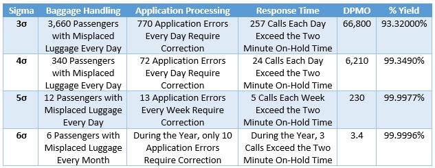
In Construction Industry anything which does not meet requirement is deemed to be called as a “Defect” and here Six Sigma Plays a pivotal role in meeting customer demand, reducing cost borne by the company, avoiding delays. Below are few staggering facts on construction industry:-
All in All main goal of Six Sigma is to manage material, time, manpower and capital efficiently and effectively Six Sigma includes providing:
By following below KPMG Six Sigma, construction industry can improve their profit & good quality of work for:-
There should be a lot of scope for Six Sigma in construction as you can statically analyse the way workers perform their site activities, knowing the numbers of skilled workers you have on your team to meet task.


The advantages of Six Sigma are still being touted. It continues to be a way of life in more and more organizations.

Some key players involved:

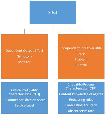
DMAIC Simplified Methodology

where D and M are Characterization, A and I are Optimization.


Elements of SIPOC


In this example, the department of Forecasting and Capacity Planning wants to create a SIPOC plan for manpower requirements. The start point of the process is the tentative forecast and the end point is the recruitment by the H R department. Let us understand how the SIPOC has been created: The first process in Forecasting and Planning involves receiving a tentative forecast. The input for this process is the forecast given by the client. So, the client here becomes the supplier. The next process is determining the staff requirements, for which the input is the shrinkage data and the supplier is the operations center. This continues till all the steps of the process are complete and the outputs are ready. In this example the outputs are the manpower indent and the manpower itself. They are handed over to the customers, who are the H R and Program.

Example:
Example:
Example:


Black Boxes indicates Defects in the above figure
Knowledge of statistics is necessary as basic statistical tools are applied to manufacturing, sales and marketing, process, equipment design, and more to improve quality and initiate cost savings right away.
Example:
A survey has been made of people’s typical daily calorie consumption, and a graph that looks like this has been plotted. Notice that the numbers for people’s typical consumption has turned out to be normally distributed. That is, for most people, their consumption is close to the average. Fewer people eat a lot more or a lot less than the mean or average. Many people obviously are neither surviving on a single serving of rice and dal nor are eating six meals of chapattis and meat. Most people lie somewhere between. Therefore, for a normally distributed data on a graph, the curve would be in the form of a bell as mentioned earlier (see below figure). The X-axis (the horizontal one), shows the calorie consumed and Y-axis (the vertical one) denotes the number of data points for each value on the x-axis. In other words, the number of people who eat x calories.

Basic Characteristics of Normal or Bell Curve:

The most commonly used method of describing central tendency. To calculate the mean, you add all the values and divide it by the number of values. (Calculation of Mean of scores = 45+34+37+42+40 = 198/5 = 39.6) So, while ‘mean signifies ‘average’, standard deviation shows the relation that a set of scores has to the mean of the sample. When the scores are tightly bunched together and the bell-shaped curve is steep, the standard deviation is small. When the scores are spread apart and the bell curve is relatively flat, that means you have a relatively large standard deviation.


Example 1:
Computing the value of standard deviation is complicated, but let us look at this example of a normal curve using the mean X bar.

One standard deviation away from the mean X bar in either direction on the horizontal axis side accounts for around 68.26% of the people in this group.
Two standard deviations away from the mean X bar account for roughly 35.46% of the people and three standard deviations account for about 99.73% of the people.
Example 2:
Let us take another example of a bell shaped curve for the Average Handling Time, or AHT, of calls.
The normal curve has a mean or average of 24 minutes. You can see the peak of the curve is the highest at that point. The standard deviation is 4 on either side of the horizontal axis. The area within one standard deviation, which is 20 to 28 minutes, accounts for 68.26%% of the given set of data. The area within two standard deviations accounts for roughly 95% of the data between 16 and 32 minutes of the average handling time. The area within three standard deviations accounts for about 99% of the data, which lies between 12 and 36 minutes at AHT.

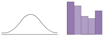
This figure shows a normal distribution, referred to as a bell shaped curve. There is a single point of central tendency and the data is symmetrically distributed about the centre (Mean) with no skewness. In normal or symmetric distribution, mean, median and mode are all the same.

Sometimes processes are naturally skewed. A distribution is skewed if one of its tails is longer than the other. Distribution when positively skewed are said to be ‘skewed to the right’. Similarly, distributions negatively skewed are said to be ‘skewed to the left’.

In a right skewed distribution, the data is less in the right tail than that expected in a normal distribution. Similarly, for a left skewed distribution, it means less data is in the left tail than expected in a normal distribution. For left or right skewed data, the median is between the mode and the mean.

Example:
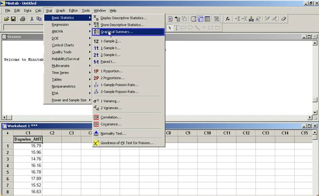
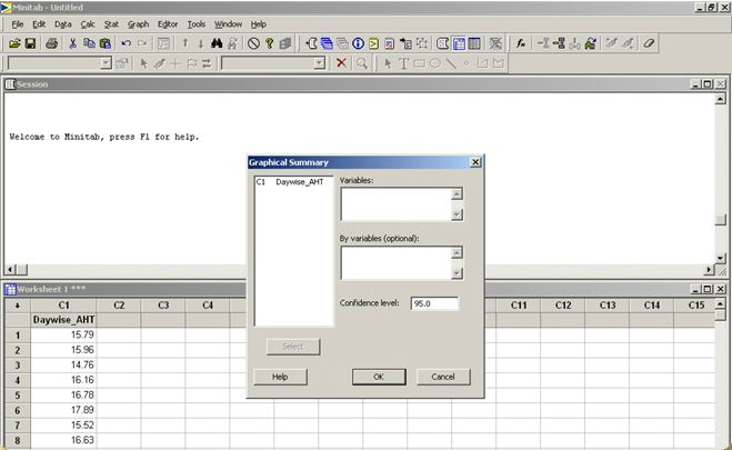
Let us consider the example of the day wise Average Handling Time or AHT in a call center to get a statistical summary of the data.


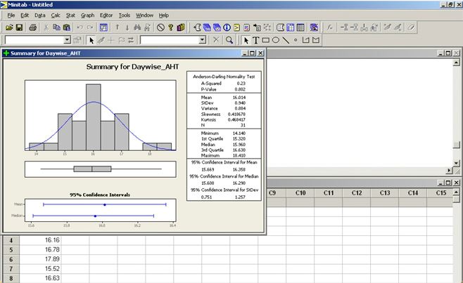


Example: Let us first learn how to create a hologram in Excel using Histogram tool of analysis, an add-in module. Using a sample table of students and their test scores, let us explore how the Histogram tool works in Excel. The scores have been broken down at 50-point intervals (taking the highest and lowest scores as outer ranges). They are arranged in ascending order in column D.


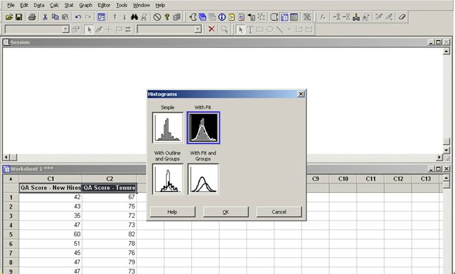
Creating Histogram using Minitab software:


Creating Pareto chart using Minitab software:


Example:
Here is some data from a call center. It relates to the QA scores of two teams – the ‘New Hires’ and ‘Tenure’. The ‘Tenure’ team comprises people who have been with the company for some time. Let us plot the data and study the stratification by creating a histogram.


Example:
Let us now study an example of CED for the problem of “Poor Soft Skills” in the organization. “Poor Soft Skills” is the key problem, shown in the head of the fish in the figure below. The four different categories of the ideas generated during the brainstorming session are language skills, courtesy or empathy, clarity, and listening skills. Each of these causes is places, accordingly, on the different bones of the fish. These causes are then further divided into sub-causes. For example, language skills are sub-divided into choice of words, phrasing of sentences, and speaking at customers’ level. Similarly, the causes of problems in clarity are bad accent, pronunciation or the speed at which the employee speaks. Thus, after examining all the causes, a decision is taken pertaining to root cause of the poor soft skills problem.


Benefits of 5 Why Analysis:
Uses of 5 Why Analysis:
Example:
Here the factor taken up is that of “Language Skills”. You can see in the below figure that the root cause has been found to be ‘Inadequate Training duration for Appropriate Modules’ after asking ‘Why’ 3 times. 
Example 1: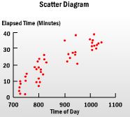
Example 2:
The scatter diagram once plotted may seem to have different forms. It is necessary to establish whether a relationship exists between the two variables or not. Let us see how to interpret scatter diagrams with different forms.

Used when:
Example:
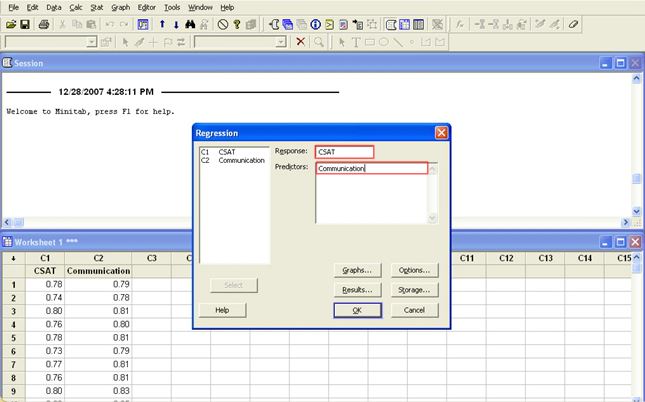
Let us see how to draw a scatter diagram using Minitab. The data selected relates CSAT scores in relation to communication skills.


Example 1:
As temperature rises, ice-cream consumption goes up in exact proportion. The hotter it gets, the more ice-cream is consumed. This is a perfect positive correlation. If you calculated correlation coefficient or ‘r’ for this data, you will get a value +1. A coefficient of -1 means perfect negative correlation, which means that when one variable increases, the other decreases.
Example 2: 
It is obvious from the graph that the longer you spend in your doctor’s waiting area, the less happy you become. In fact, happiness declines in exact proportion, as number of hours spent waiting increases. This is a perfect negative correlation. If you calculate ‘r’ for this pair of variables, you will get a value of -1. A coefficient close to zero means the variables are not related.
Example 3:
In this graph there appears to be no correlation between the two variables. A change in big toe measurement appears to have no predictable effect on the IQ of a person. There is no correlation. If you calculate ‘r’ for this pair of variables, you will get a value of 0 (zero).
Example:
Let us see an example where we can find correlation between customer satisfaction scores and various attributes of a call monitoring from Minitab.


Where Y = response, bo = predicted value of Y when X1 = O, b1 = slope of line, change in Y per unit change in X1.
Example:
Let us take the data on customer satisfaction scores and communication skills of call center agents and calculate the regression equation using the Minitab software to find out the relationship between them.


Example:
In this example, Ritz Carlton has been considered as the datum and the alternate hotels such as The Shangri-La, Jetsons, and Homor Simpson have been evaluated with respect to each criteria. If the alternate hotel has same features for a specific criteria, then we rank them as “S”, if it is superior we give a “+”, and a “-” if worse than the datum. Then the weighted sum of positives and negatives are calculated for each of the alternate hotels. 
For example, for Shangri-La, the weighted sum of positives is calculated by adding importance ranking of “Tariff” and “Spa Facilities”, which comes to 4+4=8. We can choose Shangri-La as the best alternate hotel since its weighted sum of positives is the highest compared to the other hotels.
Example:
In this example, the process step to be controlled is training delivery, and the critical input identified for this process step is training schedule. The output of this process step is percentage adherence to training schedule. The Sigma level for this process step has been calculated to be 3.5 Sigma. Training of the training adherence is done using the training tracker.  For this process step, repeatability and reproducibility are not applicable as there is no measurement gauge for measuring this metric. As adherence needs to be tracked on a real time basis for all batches, the sample size in this case is 100%, and the sample frequency is every batch conducted. Next we need to identify a method to monitor the schedule adherence during training, so that any deviation from the plan is highlighted. The control method identified in this case is the publishing of the training MIS by the process owner, who is also the training coordinator. The training coordinator would be reviewing the MIS for any deviations against the specifications. All such deviations would be escalated to the training head, so that necessary actions are taken to keep the process under control.

Flow diagram which serves as a basic guide in selecting the apppropriate control chart for the different situations:

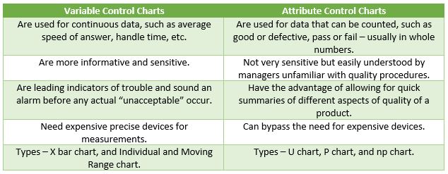
Let us look at the variable chart first:

Now, let us look at the attribute chart:

Example 1:
Example 2:
Example:
To get a clearer understanding let us analyze the QA scores taken on different days and find out whether the process is in control or not by drawing an IMR chart using Minitab.


Example:
To analyze the number of defects made on the monitored calls, let us draw a U-chart using Minitab, and verify whether the process is in control or not.


Example:
To analyze the number of defective calls, let us draw a P-chart using Minitab, and verify whether the process is in control or not.


Note:
C and Np charts are used when the data sample is constant over a period of time. In a service industry the sample size is always variable and sio these charts are not applicable.


As you can see in the above picture, the site is filled with lots of mud and resting on it are two machines viz., Pile driving machine and a Back hoe excavator.

In the above picture, the left picture shows how the building will look in day time and on right it shows how it’ll look at night time.

In the above picture, the left picture shows how the building will look in day time and on right it shows how it’ll look at night time.
There are a total of 135 piles constructed across the perimeter of site to retain the soil from collapsing as the depth of excavation is 11 meter due to Double Floor basement parking. This type of piling is called as Secant Pile Wall or Sore Piling

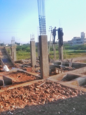
The steel reinforcement used in each pile is 10 bars of 20 mm diameter. Length of reinforcement bars is 14 meter.

A tabular pile case is first drawn in ground and with the help of hammering by piling machine, the soil is excavated from inside the pile case by boring through Piling Machine.


Grout tube adapter is kept on the pile case after inserting the reinforcement steel cage into it and then concrete is grouted in the pile case with the help of Ready Mix Concrete which is shown in next image.


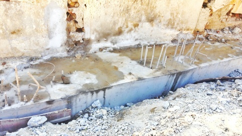
M10 Grade Concrete is used while laying P.C.C


M30 Grade Concrete is used while concreting the Grade Beam