CHAPTER-I
GENERAL PHILOSOPHY OF BUILDING DESIGN
DESIGN OF R.C.C. MEMBERS OF BUILDINGS, PROCEDURE FOLLOWED IN THE DESIGNS CIRCLE.
-
INTRODUCTION:
Instructions about the preparation of R.C.C design of building works have been issued vide Govt. in P.W.D. Circular No.BDG-1080/ 80838 (394)/Desk-2, dt.3rd Nov.1980.
- This circular states that R.C.C. design of all load bearing structures and R.C.C. framed structures up to four stories i.e. G+3 upper, except in case of structures requiring wind and/or seismic analysis, shall be prepared by the field engineers.
- The design of R.C.C. frame structures having more than G+3 upper floors as well as structures with more that G+2 upper floors requiring wind and/or seismic analysis are required to be prepared by Design Circle.
- Designs Circle will undertake the work of preparing R.C.C. design for a structure only after the receipt of the following information from the field engineers.
(a) Copy of Administrative approval to the estimate of the structure, (based on approved Architectural drawings.) along with a blue print set of original Architect’s plans (No traced copies are acceptable).
(b) Copy of Technical sanction from the competent authority.
(c) If the work is budgeted, item number of work and its page number in the Budget Book.
(d) Proposed construction programme i.e. proposed dates of start of different stages of construction and scope of different phases of construction, in case of phased construction.
(e) “Field Data” in standard proforma prescribed by the Designs Circle. Copy of the standard proforma is kept at page 48 . - It is also desired that Field Engineer should communicate to Designs Circle, the present position of the tender for the work i.e. the date of issue of tender notice, date of receipt of the tender and likely date of issue of work order. This information will be helpful to Designs Circle, in planning the design work and there will be less likelihood of delay in supply of R.C.C. Schedules from time to time i.e. as per the construction programme proposed by field engineers.
- It is a prerequisite that, before undertaking actual design work, the design engineer should have basic knowledge of “Strength of materials”, “Properties of materials”, “Behaviour of structures,”, “Analysis of structures” and thorough knowledge about detailing of reinforcement, etc. Also he should be acquainted with various I.S. Codes which are required to be referred to in the design work. It is, therefore, advised that the designer should refresh his knowledge by referring to the various technical books and codes.
- DESIGN PHILOSOPHY :
- R.C.C. design of building is being carried out mainly (1) Limit state method.
- The Limit state method is now in vogue in all government design offices and premier private consulting firms. The B.I.S. have published I.S.:456-2000 incorporating the use of Limit State Method as a main philosophy of design. The designer should therefore get well versed with the theory of Limit State Method of design.
Working Stress Method: Used over decades, this method is now practically outdated in many advanced countries of the world, because of its inherent limitations.
The I.S.:456-2000 code gives emphasis on Limit State Method which is the modified form of Ultimate Load Method.
Limit State Method is a judicious amalgamation of Working Stress Method and Ultimate Load Method, removing the drawbacks of both the methods but retaining their good points. It is also based on sound scientific principles and backed by more than 25 years of research. The Limit State Method has proved to have an edge over the Working Stress Method from the economic point of view. Consequently we need not stick to Working Stress Method any more. Accordingly, Designs Circle in P.W. Department is designing the R.C.C. structures as per Limit State Method, since early eighties.
- Codes: In carrying out the design calculations, one has to comply to the provisions of various I.S. Codes. Use of special publications of B.I.S. and Hand Books for design methodology and readymade design tables can also be made. A List of frequently referred codes/hand books is given on page 7.
- The designer is advised to study I.S. codes carefully and also discuss the provisions among his colleagues/superior officers for clarification/s for better understanding.
- Besides analytical part of structural design, following factors should also be kept in mind while designing the structure.
(a) Strength of structure.
(b) Durability of structure.
(c) Serviceability of structure, during construction as well as during design life time of the structure.
(d) Economy in building materials ease of construction and maintenance.
(e) Economy in centering and form work.
(f) Aesthetics of structure.
- COMPUTER AIDED DESIGN :
- Personal computers of sufficiently high speed and large memory capacity have been made available to Designs Circle. Designs Circle has developed various design software and same are being used. Software available presently in Designs Circle are discussed in Chapter IV. Designer should get conversant with the Users Manuals of these programmes so that he can work independently on the computer.
At present mainly STAAD. Pro /Struds are being used for design of buildings in Designs Circle.
- STEPS INVOLVED IN R.C.C. DESIGN :
The R.C.C. design of a building is carried out in following steps:
(i) Study the architectural drawings.
(ii) Study the field data.
(iii)Prepare R.C.C. layouts at various floor levels.
(iv) Decide the imposed live load and other loads such as wind, seismic and other miscellaneous loads, (where applicable), as per I.S.:875, IS 1893-2000 considering the contemplated use of space, and seismic zone of the site of proposed building.
(v) Fix the tentative slab and beam sizes and then prepare preliminary beam design. Using values of support reactions from preliminary beam design, prepare preliminary column design and based on these load calculations, fix tentative column section and it’s concrete mix. As far as possible, for multistoried buildings, the same column size and column mix should be used for at least two stories so as to avoid frequent changes in column size and concrete mix facilitate easy and quick construction. Concrete Mix to be adopted for beams and slabs as per IS :456-2000 page No.20.
(vi) Group the members such as columns, beams, slabs, footings etc. wherever possible, on the basis of the similarity of loading pattern, spans, end conditions etc. It reduces the quantum of calculation work. (vii) Prepare R.C.C. Layouts and get approval from the Architect to the R.C.C. layouts and tentative sizes of beams and columns and other structural members if any. In the R.C.C. layouts, show the structural arrangement and orientation of columns, layout of beams, type of slab (with its design live load) at different floor levels.
For a building, generally following R.C.C. layouts are prepared.
(a) R.C.C. layout at pile cap/plinth level/tie level (if any).
(b) R.C.C. layout at various floor levels or at typical floor level (depending on Architectural plans).
(c) R.C.C. layout at terrace level.
(d) R.C.C. layout at staircase roof level.
and where lifts are provided.
(e) R.C.C. layout at lift machine room floor level.
(f) R.C.C. layout at lift machine room roof level.
Where good foundation is available at reasonably shallow depth, provision of plinth beams in Non Seismic Areas can be omitted. However, this should be got approved from Superintending Engineer/competent authority. In such case the R.C.C. layout at plinth level may be prepared accordingly.
(viii) Finalise various structural frames in X-direction and Y-direction followed by preparation of frame sketches and filling in, data of the frames on coding sheets, for computer aided frame analysis.
(ix) Feed the data of frames on computer and recheck the data so stored, by getting a print out.
(x) Analyse the frames using STAAD Pro.
(xi) Calculation of Horizontal forces : Whenever the structure is to be designed for horizontal forces (due to seismic or wind forces) refer I.S.:1893 for seismic forces and I.S.:875 Part-III for wind forces.
All design parameters for seismic/wind analysis shall be got approved from Superintending Engineer before starting design calculations and frame analysis. The proper selection of the various parameters is a critical stage in design process.
(xii) Design column sections Assemble the design data for column design, using results obtained in analysis of respective X and Y direction frames, which include the column under considerations. The design of column can be done using computer programme “ASP2” or manually by referring to ‘Hand Book of R.C.members (Limit State Design) Volume II’ (Govt. of Maharashtra Publication).
(xiii) Design footings manually using ‘Hand Book of R.C.C. members (Limit State Design) Volume II’ or by using the computer programme ‘FOOT’ or other suitable programme Software for design of isolated or combined footing. For design of other types of footing refer standard text books.
(xiv) Design slabs manually by using ‘Hand Book for R.C.members Vol.I’ or by using computer programme ‘SLAB’.
(xv) Design beams by using the frame analysis output. It gives required area of reinforcement at various locations and diameter and spacing of shear reinforcement. Ductility shall be applied for building in Seismic Zone III & IV above.
Designer’s work now involves.
(a) Fix the bar diameter and number of bars (at top and bottom) at various locations along the beam span, as per codal provisions and practice.
(b) Finalise the diameter and spacing of shear reinforcement as per analysis results and as per codal provisions of detailing where ever applicable.
(xvi) Preparation of R.C.C. schedules for footings, slabs, beams and columns at various levels, on completion of respective design.
As these R.C.C. schedules are to be used during the execution, designer should take maximum care in preparing them. Schedules should be prepared by one Engineer, and thoroughly cross checked by another Engineer, before submitting the same for approval to the competent authority. In schedules, special instructions to the field engineers should be highlighted and sketches should be drawn wherever necessary.
CHAPTER-II
PREREQUISITES OF BUILDING DESIGN
- STUDY OF ARCHITECTURAL DRAWINGS :
- As the building is to be constructed as per the drawings prepared by the Architect, it is very much necessary for the Designer to correctly visualize the structural arrangement as proposed by the Architect. A Designer, after studying Architect’s plans, can suggest necessary changes like additions / deletions and orientations of columns and beams as required from structural point of view.
- For this, the designer should have a complete set of prints of original approved architectural drawings of the building namely i) Plans at all the floor levels, ii) Elevations, (front, back and sides), iii) Salient cross sections where change in elevation occurs and any other sections that will aid to visualize the structure more easily. The cross sections should show the internal details like locations of windows, doors, toilets, staircases, lift machine room, staircase rooms, and any other special features like gutter at roof level, projections proposed to give special elevation treatment, etc.
- During the study following points should be noted. The drawings should be examined to find out,
(i) Whether the plan shows all the required dimensions and levels so that the designer can arrive at the lengths and sizes of different members. Wherever necessary, obligatory member sizes required by Architect (on architectural grounds) are given or otherwise.
(ii) Whether the plans and schedules of doors and windows etc. are supplied so as to enable designer to decide beam sizes at these locations.
(iii) Whether thickness of various walls and their height is given. Head room in stair and ramp, porch basement should be checked with reference of required depth of beam.
(iv) Whether functional requirements and utility of various spaces are specified in the plans. These details will help in deciding the imposed load on these spaces.
(v) Whether material for walls is specified.
(vi) The structural arrangement and sizes proposed by the Architect should not generally be changed except where structural design requirements can not be fulfilled by using other alternatives like using higher grade of concrete mix or by using higher percentage of steel or by using any other suitable alternate structural arrangement. Any change so necessitated be made in consultation with the Architect. Further design should be carried out accordingly. (vii) Note the false ceiling, lighting arrangements, lift/s along with their individual carrying capacity (either passenger or goods), Air Conditioning ducting, acoustical treatment, R.C.C. cladding, finishing items, fixtures, service/s’ opening proposed by the Architect.
(viii) Note the position/s of expansion joints, future expansion (horizontal and / vertical) contemplated in the Architect’s plan and check up with the present scope of work (indicated in the “Field Data” submitted by the field engineers). The design of the present phase will account for future expansion provision such as loads to be considered for column and footing design (combined / expansion joint footing) resulting if any.
If this aspect is neglected it will create design as well as execution problems in the next phase of work. In case of vertical expansion in future, the design load for the present terrace shall be maximum of the future floor level design load or present terrace level design load.
(ix) Whether equipment layout has been given, particularly in the areas where heavy machinery is proposed to be located.
(x) Special features like sun breakers, fins, built-in cupboards with their sections so as to enable designer to take their proper cognizance. (xi) Whether the location/s of the over head water tanks specified by the Architect and whether “Field Data” submitted by field engineer furnishes the required capacity of each over head water tank.
(xii) What type of water proofing treatment is proposed in toilet blocks and on terrace.
The findings of the above scrutiny should be brought to the notice of the Architect and his clear opinion in this matter should be obtained before proceeding ahead with R.C.C. design.
- STUDY OF FIELD DATA :
- The architectural drawings give the details only from architectural point of view. As such the designer must also have thorough information of the site where the structure is proposed to be constructed. For this a standard proforma has been prescribed by Designs Circle. The field engineer has to submit the field data in this proforma while requesting Designs Circle for supply of R.C.C. designs. Copy of the form of “Field Data” is kept as page 48.
- The “Field Data” is essential before starting design work. However, it is generally noticed, that the “Field Data” lacks vital information such as bearing capacity of the founding strata, proposed location and capacity of over head water tank/s, electrical lift loads, future horizontal and/or vertical expansion etc. So on receipt of “Field Data” it should be checked thoroughly and if any data is found to be missing, the same should be called from field engineer immediately, to avoid delay in starting the design work.
- Besides information on the points mentioned in prescribed proforma, information on special points also is to be supplied where applicable by the field officers, like : (i) Machinery and/or equipment layout.
(ii) Air cooling/air conditioning ducting layouts including exhaust arrangements.
(iii) False ceiling arrangements, proposed acoustical treatment, electrical lighting and audio system fixtures.
(iv) Fire fighting pipeline/s or any other special ducting layouts.
(v) Sub soil and sub soil water properties particularly Sulfide and Chloride contents where the building is located in coastal and or highly polluted industrial area.
(vi) Importance factor (I) and zone factor as per I.S.1893; to be considered for the proposed building when the building is being constructed in seismic zone. It may be noted that the importance factor more than 1.0 leads to increased seismic forces consequently the reinforcement requirement increases considerably. Therefore before starting Seismic Analysis, importance factor (I) should be got approved from the Superintending Engineer.
(vii) In case foundations other than open type of foundation proposed (with reasons) and safe bearing capacity of the founding strata and its depth from the general ground level alongwith trial bore log details and test results on rock samples.
(viii) If necessary, Superintending Engineer, Designs Circle shall visit the site, in case of critical site OR field data is inadequate.
- LIST OF I.S. CODES GENERALLY REQUIRED TO BE REFFERED TO FOR BUILIDNG DESIGN.
- The important I.S. Codes (with their latest editions/amendments) to be referred to for design of buildings are as follows :
(i) I.S.:456-2000 : Code of practice for plain and reinforced concrete.
(ii) I.S.:800-1962 : Code of practice for use of structural steel in general building construction.
(iii) I.S.:875-1987 : Design loads (Part I to V) other than earthquake for building design.
Part-I : Dead loads. Part-II : Imposed loads. Part-III : Wind loads. Part-IV : Snow loads. Part-V : Special loads and load combinations. (iv) I.S.:1080-1965: Code of practice for Design and construction of shallow foundation in soils (other than Raft, Ring and Shell)
(v) I.S.: 1642-1988: Fire safety of Bldgs. (General) Details of Construction.
(vi) I.S.:1643-1988: Code of Practice for Fire safety of Bldgs. (General) Exposure Hazard.
(vii) I.S.:1644-1988: Code of practice for fire safety of Bldgs. (General) Exit requirements and personal Hazards.
(viii)I.S.:1888-1972:Methods of load test on soils.
(ix)I.S.:1893-(Part 1): Criteria for 2002 earthquake resistant design of structures.
(x) I.S.:1904-1986: Code of practice for design & construction of foundation in soil structural safety of building foundation. (xi) I.S.:2911:1990: Code of practice (Part I to IV) for design and construction of pile foundation.
(xii) I.S.:2950-1981: Code of practice for design and construction of raft foundation.
(xiii) I.S.:3370-1965: Code of practice for water retaining structures.
(xiv) I.S.:3414-1987: Code of Practice for Design and installation of joints in Buildings.
(xv) I.S.:4326-1993: Code of practice for earthquake resistant design of structure.
(xvi) I.S.:6403-1981: Code of Practice for Determination of bearing pressure of shallow foundation.
(xvii) I.S.:13920-1993: Code of (reaffirmed practice for 1998) ductility detailing of reinforced concrete structures subjected to seismic forces. I.S. Codes are also available for design of special types of structures like folded plate, shell structures etc. Refer Publication list of BIS for the same.
Similarly there are special publications of I.S. which are useful for design of buildings such as.
(i) SP-16 : Design Aids to I.S.:456-2000.
(ii) SP-22 : Explanation of I.S.1893 & I.S.:4326.
(iii) SP-23 : Concrete Mix.
(iv) SP-24 : Explanation of I.S.:456-2000.
(v) SP-25 : Cracks in buildings and their repairs.
(vi) SP-34 : Detailing in R.C.C. structures.
(vii) SP-38 : Design of steel trusses.
Besides above mentioned I.S. Codes “Hand Book for R.C.Members” (Limit State Design) Vol.I.and II by P.L. Bongirwar and U.S.Kalgutkar, published by P.W.D. (Govt. of Maharashtra) is very useful.
For aspects which are not covered by any other I.S. codes available, relevant British Standard codes may be referred to.
- While designing R.C.C. structures, important provisions of I.S.Codes must be borne in mind. Some of the important provisions of I.S.:456-2000 are as follow :
- General Provisions : Clause No.20 : Deals with stability of the structure against overturning and sliding. Clause No.26.2.1 : Development length of bars.
Clause No.26.3.2: Minimum distance between individual bars.
Clause No.26.3.3: Maximum distance between bars in tension.
Clause No.26.4 : Nominal Cover to reinforcement.
Clause No.27 : Expansion joints.
- Provision regarding slabs :
Clause No.22.2 : Effective span.
Clause No.22.4.1: Arrangement of Imposed load.
Clause No.22.5 : Moment and shear co-efficient for continuous beams.
Clause No.23.2 : Control of deflection.
Clause No.24.1 : Provisions regarding solid slabs. Clause No.26.5.2.1: Minimum reinforcement.
Clause No.26.5.2.2: Maximum diameter. - Provisions Regarding Beams :
Clause No.22.2 : Effective span.
Clause No.22.4.1: Arrangement of live load.
Clause No.22.5 : Moment and Shear co-efficient for continuous beams.
Clause No.23.2 : Control of deflection.
Clause No.23.3 : Slenderness Limits for beams.
Clause No.26.5.1.1: Requirement of tensile reinforcement for beams.
Clause No.26.5.1.2: Compression reinforcement.
Clause No.26.5.1.3: Side face reinforcement.
Clause No.26.5.1.5: Maximum Spacing of shear reinforcement.
Clause No.26.5.1.6: Minimum shear reinforcement.
Clause No.26.5.1.7: Distribution of torsion reinforcement.
- Provisions for Columns :
Clause No.25.1.2: Short and slender compression members. Clause No.25.1.3: Unsupported length.
Clause No.25.2 : Effective length of compression members.
Clause No.25.3: Slenderness limits for columns.
Clause No.25.4 : Minimum eccentricity.
Clause No.26.5.3.1: Longitudinal reinforcement.
Clause No.26.5.3.2: Transverse reinforcement.
Clause No.43 : Cracking consideration.
- Provisions for footings :
Clause No.34.1.2 : Thickness at the edge of footing. Clause No.34.4 : Transfer of load at the base of columns.
Other references / Literature generally referred to are
1.Reinforced Concrete Designer’s Hand Book by Reynolds & Steelman. 2.Limit State Theory & Design of Reinforced Concrete by Karve and Shah. 3.Hand Book of Reinforced Concrete Design (I.S.455-1978) by Karve. 4. Limit State Design of Reinforced Concrete by Vergis.
- GENERAL PRACTICE FOLLOWED IN DESIGNS CIRCLE :
(i) The loading to be considering for design of different parts of the structure including wind loads shall be generally as per I.S.:875-1987 (Part I to IV) and I.S.:1893-2002 (seismic loads) with their latest amendments/s.
(ii) Live load for sanitary block shall be 200 kg/m2.
(iii) Lift machine room slab shall be designed for live load of 1000 kg/m2.
(iv) Lift loads shall be considered as per relevant I.S. codes as per capacity of lift and the same shall be increased by 100% for impact while designing.
(v) Loading due to electrical installation e.g. A.C. ducting, exhaust fans etc. shall be got confirmed from the Executive Engineer, electrical wing of P.W. Department.
(vi) Seismic loads shall be as per I.S.:1893-2002 and I.S.43261993. The method of analysis and values of various parameters shall be taken as per relevant provisions of the codes.
(vii) Ductility provisions specified in I.S.:4326-1993 and I.S.:13920-reaffirmed 1998 Edition 1.2, 2002-2003 shall be adopted in design, for the buildings located in Seismic Zone III, IV & V.
(viii) Any other loads which may be required to be considered in the designs due to special type or nature of the structure shall be got approved in advance from the Superintending Engineer.
(ix) Deduction in dead loads for openings in walls need not be considered.
(x) Unless otherwise specified, the weight of various materials shall be considered as given below :
(a) Brick masonry :1920 kg/m3
(b) Reinforced cement :2500 concrete kg/m3.
(c) Floor finish for : 100 heavy weight suitably kg/m2 added and for light weight subtracted.
(d) Brick Bat Coba of : 200 112 mm. thickness kg/m2 laid on terrace for water proofing treatment.
(e) Brick Bat Coba in :1920 bath & W.C. kg/m3. depending on thickness of water proofing treatment .
(xi) The analysis shall be carried out separately for dead loads, live loads, seismic loads, wind loads. All the structural components shall be designed for the worst combination of the above loads as per I.S.:1893-2002.
(xii) Minimum reinforcement in all structural members shall be as per relevant clauses of I.S.: 4562000.
(xiii) The R.C.C. detailing in general shall be as per SP:34 and as per the sketches given in this guidelines. (xiv) High Yield Strength Deformed bars shall be used for main and distribution reinforcement.
(xv) Diameter of bars in footings, shall be not less than 10 mm.
(xvi) Spacing of stirrups in beams shall not exceed 25 cm.
(xvii) Thickness of slab shall not be less than 12 cm. and in toilet blocks not less than 15 cm.
(xviii) Depth of beam shall not be less than 23 cm.
(xix) Spacing of ties in columns shall not exceed 25 cm.
(xx) The longitudinal bars in columns shall not be less than 12 mm. in diameter.
CHAPTER-III
GENERAL PROCEDURE OF DESIGN
- GUIDELINES FOR PREPARATION OF R.C.C. LAYOUTS.
- The preparation of R.C.C. layouts involves fixing of locations of columns and beams, denoting slabs with respect to design live load, type of slab and numbering these structural elements.
- There are two types of joints which need to be considered in the layouts. They are (a) movements joints, (b) Expansion joints.
- If the length of building exceeds 45 m., expansion joints shall be provided to split it into suitable parts which are individually less than 45 m. in length. Building having wings in different directions shall be provided with expansion joints at the connection of the wings to central core to avoid torsional effects. Expansion joints may also be provided when there is a sudden change in plan dimensions. For details of the joints refer to I.S.:3414-1968, I.S.:4326-1976 and I.S.:3370-1965 (Part-I), I.S.:1893-2000.
- In case the building is having different number of stories for different parts of the building, thus having different dynamic characteristics, then such parts shall be kept separated by a movement joint to avoid unequal loading, unequal settlement and collusion during an earthquake. Movement joints may also to be provided if the different parts of building are located on different stratas and of different safe bearing capacities. Such movement joints, however shall be provided right to the bottom of the foundation, unlike the expansion joints which are provided only upto the top of the foundation. In this regard refer to S.P.34, (explanatory Hand Book of I.S.:456-2000 clause 27 and also refer clause 5.1.1 of I.S.:43261993. As per this clause the minimum total gap between these joints shall be 25 mm.
- Separate R.C.C. layouts are to be prepared for different levels i.e. plinth, typical or at each floor level (if the plans are not identical at all floor levels) terrace floor level, staircase block roof level and where applicable lift machine room floor level, lift machine room roof level, water tank bottom level.
- R.C.C. layouts are generally prepared on tracing paper from the architectural drawings, by tracing only the walls, columns and other structural members. In the layout, the door and window positions are not shown.
- NUMBERING SYSTEM AND NOTATIONS TO BE ADOPTED IN LAYOUTS
- Columns:
Columns are numbered serially with integer number suffixed to letter “C” i.e. C1, C2, C3 etc. The columns are numbered from lower most left corner of the R.C.C. layout. Numbering shall proceed from left to right in X direction and proceeding successively in positive ‘Y’ direction. R.C.C. layout showing column numbering is kept as page 43. - Beams :
(i) Beam actually supported over a column is called main beam. Beam supported over other beam is called secondary beam.
(ii) A beam number is composed of two parts e.g.5.1, 5.2 etc. The part to the left of decimal point denotes the left side reference column number. The part to the right represents serial number of the beam.
Beams in X direction here the reference column is left supporting column. If left supporting column is absent then right supporting column is considered as reference column. For X direction beam serial number (2nd part) is always odd e.g. 1, 01, 3, 03 etc. Beams to the right side of reference column is numbered as 5.1 etc. While beams to the left of reference column is numbered as 5.01, where the reference column is C 5.
Beams in ‘Y’ direction in this case reference column is bottom most column. If the bottom column is absent then the upper supporting column can be considered as the reference column. For Y direction beam serial number (2nd part) is always even number e.g.5.2, 5.02, 5.4 etc. Beams in positive Y direction of reference column are numbered as 5.2 while beams in negative Y direction of the reference column are numbered as 5.02, where the reference column number is C 5. - For numbering the secondary beams in “X” direction the first part of beam number shall be a reference column which shall be the nearest left side column of the beam. The second part shall be odd number except ‘1’ i.e. 3, 5 etc. serially in X direction. e.g.5.3, 5.5 etc.
Similarly secondary beams in Y direction can be numbered e.g. 5.4, 5.6 etc. except “2”. - If the beams are at intermediate level above the floor under consideration then the beam number will be suffixed with a letter like A, B & M. e.g. If 5.1 is main beam at 1st floor level, 5.1 A is a beam in X direction at 1st floor lintel level, and 5.2 M is a beam in Y direction at MID-LANDING LEVEL between the 1st floor and 2nd floor levels. “A” refers to floor level and “B’ refers to lintel level and “M” refers mid-landing level.
- Slabs :
The slab notation is composed of four parts. The first, second and third part are written on the left side of the decimal point and the 4th is written on the right hand side of the decimal point e.g. 200S1.1, 500S2.2.
(i) The first part denotes the imposed live load intensity in Kg./sqm. for which the particular slab is designed. This load is decided on the basis of designated use of the particular space (the slab) as shown in the Architect’s plans and as per provisions of I.S.875. This practice is useful and advantageous for maintaining a proper record especially when different slab panels are designed for different live loads. This record is also useful to avoid over loading of the slab in future change of usage.
(ii) The second part represents the type of the slab fore e.g.
“S” denotes general floor slab, “SF” denotes staircase flight slab, “SR” denotes room roof level slab / staircase room roof level slab, “SM” denotes machine room floor slab “SC” denotes cantilever slab and “ST” denotes terrace slab.
(iii) The third part is either “1” or “2” , “1” denotes the slab is one way. The “2” denotes the slab is two way.
(iv) The fourth part is the serial number of the slab in one way/two way category. Slabs having different end conditions shall be treated as different slabs for this notation.
(v) Slabs shall be grouped on the basis of panel dimensions, loading pattern and end conditions.
(vi) The notation for one way slab, two way slab, 23 cm. brick wall, 15 cm. thick brick wall, R.C.C. pardi is shown on sample R.C.C. layout kept at page 43. The dead load of various structural material and live loads adopted for different slabs and the R.C.C. layouts shall be got approved from Superintending Engineer. - GUIDELINE FOR FIXING THE POSITION AND ORIENTATION OF COLUMNS IN THE LAYOUT.
This is an important stage. It is skillful job and economy in design is achieved by locating columns at proper and/ideal locations.
(i) Normally the positions of the columns are shown by Architect in his plans.
(ii) Columns should generally and preferably be located at or near corners and intersection/junction of walls.
(iii) If the site restrictions make it obligatory to locate column footings within the property line the column may be shifted inside along a cross wall to accommodate footings within the property line. Alternatively trapezoidal footing, eccentric footing can also be adopted.
In residential buildings, generally columns should be located at 3 to 4 m.c/c. to avoid large spans of beam. This will also control deflection and cracking.
(iv) While fixing the orientation of columns care should be taken that it does not change architectural elevation. This can be achieved by keeping the column orientations and side restrictions as proposed in plans by the Architect. (v) As far as possible, column projection/s outside the walls should be avoided, unless Architect’s plans show contrary or same is required as structural requirement.
(vi) Columns should not obstruct door and window position/s shown in the Architect’s plans.
(vii) As far as possible columns should be so positioned, that continuous frames from one end to the other end of building in both X and Y directions are available. This will increase the global stiffness of the building against horizontal forces.
(viii) When the locations of two columns are near to each other (for e.g. the corner of the building and intersection of the walls) then as far as possible only one column should be provided or secondary beam shall be provided.
(ix) As far as possible columns should not be closer than 2m. c/c to avoid stripped/combined/continuous footings. Generally the maximum distance between two columns should not be more that 8m. c/c.
(x) Column should be normally provided around staircases and lift wells.
(xi) Preferably overhead water tank should rest on the columns as shown in the Architect’s plan. The height of water tank should be upto 2.0 m. Clear height between top of Terrace and Bottom of water tank should not be less than 0.90 m.
(xii) Twin columns of equal size are desirable at expansion joints from aesthetic point of view. (xiii) As far as possible every column must be connected (tied) in both directions with beams at each floor level, so as to avoid slender columns.
(xiv) As far as possible columns supported on beam should be avoided. (Such columns are commonly called as floating columns)
(xv) When columns along with connecting beams form a frame, the columns should be so orientated that as far as possible the larger dimension of the columns is perpendicular to the major axis of bending. By this arrangement column sections and there reinforcement are utilized to the best structural advantage. - GUIDELINES FOR FINALISING THE BEAM POSITIONS :
(i) Normally beams shall be provided below all the walls.
(ii) Beams shall be provided for supporting staircase flights at floor levels and at mid landing levels.
(iii) Beams should be positioned so to restrict the slab thickness, to 15 cm, satisfying the deflection criteria. To achieve this, secondary beams shall be provided where necessary.
(iv) Generally we come across with the situation that there is a gap between the floor level beam and beam supporting the chajja. Here the depth of floor beam shall be so chosen that it can support chajja also. However if depth so required is large (distance between floor beam bottom and lintel top, greater than 30 cm) provide separate beam. (v) As far as possible, cantilever beams should not be projected from beams, to avoid torsion.
(vi) Beams of equal depths shall be provided on both sides of the expansion joint from aesthetic point of view.
(vii) To get the required minimum head room, following alternatives can be tried. (a) Reduce the beam depth without violating deflection criteria and maximum percentage of steel criteria for beams.
(b) In case there is a wall, over the beam without any opening, inverted beam may be provided in consultation with Architect.
(viii)Where secondary beams are proposed to reduce the slab thickness and to form a grid of beams, the secondary beams shall preferably be provided of lesser depth than the depth of supporting beams so that main reinforcement of secondary beams shall always pass above the reinforcement of main beams.
(ix)In toilet block provide minimum number of secondary beams so that casting of slabs and beams will be simple. ‘No secondary beam’ condition would be ideal. (x) Beams which are required to give a planer look from the underside shall be provided as Inverted Beams, e.g. canopies. - GUIDELINES FOR FIXING THE SLAB DIRECTIONS :
(i) Slab shall be designed as one way slabs if ratio of Ly to Lx is more than 2 and two way slab, if the ratio is equal or less than 2. Where Lx is shorter span and Ly is longer span of the slab.
(ii) However as per Designs Circles practice slabs upto 2.5 m. spans may be designed as one way slabs.
(iii) Canopy, Chajja, balcony slabs are generally provided as cantilever slabs.
(iv) W.C. slab is generally made sloping or sunk by about 50 cm. OR as indicated in architect’s drawing below general floor level for Indian type water closet. Slabs for toilet block and Nahani slab are generally sunk by 20 cm. OR as indicated in architecture’s drawing below general floor level.
(v) Staircase waist slab shall be generally one way slab.
(vi) Loft slabs over toilets are generally supported on partition walls of toilet and W.C. Loft load should be considered while designing the beams supporting these walls. - PRELIMINARY BEAM DESIGN (P.B.D.) All secondary beams may be treated a simply supported beams.
- Begin with fixing the dimensions of beam. The width of the beam under a wall is preferably kept equal to the width of that wall to avoid offsets i.e. if the wall is of 23 cm. then provide beam width of 23 cm.
- Minimum width of main and secondary beam shall 23 cm. However secondary beams can be of 15 cm. in case of beams of toilet block. The width of the beam should also satisfy architectural considerations.
- The span to depth ratio for beam be adopted as follows :
For Buildings in seismic zone between 10 to 12 and for non-seismic zone 12 to 15.
In case of Building located in Seismic Zone III, IV, V width to depth ratio shall be more than 0.30. The depth so calculated shall be as shown in the Architect’s plan. - To limit deflection, of a beam (up to 10 m. span) within the permissible limit, under service load, the I.S.:456 clause 23.2.1 provides the following span to depth ratios.
(i) For cantilever not more than 7
(ii) For simply supported beam not more than 20.
(iii) For continuous beam not more than 26.
These ratios can be further modified according to Modification Factor depending upon percentage steel used in the section as per I.S.:456 clause 23.2.1 (e). - The beams shall be designed as deep beam/slender beam as the case may be.
- The beam shall be treated as
(i) A rectangular beam if it does not support any slab on either side also if it is an inverted beam.
(ii) As “L” beam if it supports a slab on one side and (iii) As “T” beam if it supports slab on both sides. - Arrangement of imposed load :
(a) Consideration may be limited to combinations of :
(i) Design dead load on all spans with full design live load on two adjacent spans.
(ii) Design dead load on all spans with full design live load on alternate spans.
(b) When design live load does not exceed 75% of the Design Dead load, the loading arrangement may be, Design Dead load and Design live load, on all spans. - For beams and slabs continuous over supports, Load combinations given in 5.7 above may be assumed.
- STAAD and Struds software is used for design.
- PRELIMINARY COLUMN DESIGN AND DETERMINATION OF SIZE OF COLUMN SECTION : (P.C.D.)
- The dimensions of a particular column section, is decided in the following way :
(i) A column shall have minimum section 23 cm. x 23 cm. if it is not an obligatory size column.
(ii) The size of the obligatory column/s shall be taken as shown on the architect’s plan. For non obligatory columns as far as possible the smaller dimension shall equal to wall thickness as to avoid any projection inside the room. The longer dimension should be chosen such that it is a multiple of 5 cm. and ratio Pu/fck bd is restricted to, for non-seismic area 0.4 (for corner columns it may be 0.35) and for seismic region 0.35 (for corner columns it may be 0.30).
Where Pu, Fck, B, D have the following meaning :
Pu is the factored load on the column. (in Newton)
Fck is characteristic compressive strength of concrete. (Newton/mm2)
b is the breadth of the column (mm).
d is the depth of the column (mm) - The above ratios will ultimately help in keeping the requirements of steel for column within 0.8 to 2.5% which is economical and will avoid congestion of steel. Generally the concrete mix in R.C.C. work shall be as per Table No.5 of I.S.:456-2000. For moderate exposure condition M- 20 for R.C.C. and for severe exposure condition minimum grade shall be M-30.
- If the size of a column is obligatory or if size can not be increased to desired size due to Architectural constraints and if the ratio of Pu/fck bd works out to be more than the limit specified above it will be necessary to upgrade the mix of concrete. For ease of construction frequent changes in column size should be avoided. As far as possible in multistoried building at least two floors should have the same column section. Preferably least number of column sizes should be adopted in the entire building and mix of all the columns on a particular floor should be same.
- Effective length of column shall be calculated as per figure 26 and 27 of I.S.456-2000.
- Columns shall be designed for direct load and uniaxial or biaxial bending considering different for load combinations as given in I.S.:456:2000.
- Grouping of columns can be done on the basis of size, orientation and forces acting on it.
- All R.C.C. layouts, tentative sizes of beam, and column sections should be got approved from the Architect before starting analysis of frames.
- ANALYSIS OF BUILDING FRAMES
- In Designs Circle, at present, space analysis is done by treating the building as composed of only plane frames.
A building may be required to be designed for Non Seismic/- Seismic Forces and/wind forces (whichever is governing) depending on the location, plan dimensions and height of the building. - An another software STRUDS is available in the Designs Circle. The same is used for small buildings.
- The other inhouse programmes “FOOT”, “EC FOOT”, “SLAB”, “ASP2” are available. These Programmes are used for design of various components such as Isolated Footing, Combined Footing, Slab and Columns.
- For buildings located in all Seismic Zone, seismic analysis is required to be carried out and ductile detailing is not done for Zone I & II.
- The magnitude of seismic nodal horizontal forces are worked out.
Before starting the analysis of frames the forces for which the building is to be designed and the design parameters and particularly Importance Factor (I) and for Seismic Design to be adopted approved from Superintending Engineer.
CHAPTER-IV
STRUCTURAL MODEL AND SEISMIC ANALYSIS
- SEISMIC ANALYSIS
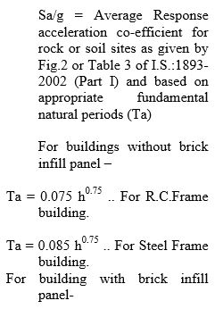
- For Calculating seismic forces refer provisions of I.S.:1893-2002 (PART I)
- It should be noted that provisions of I.S.:1893-2002 (Part I) are applicable to buildings, elevated structures, industrial and stack like structures, bridges, concrete masonry and earth dams, embankments and retaining walls and other structures.
Temporary elements such as scaffolding, temporary excavations need not be designed for earthquake forces. - Dynamic analysis shall be performed to obtain the design seismic forces and its distribution to different levels along the height of the building, for the following buildings :
a) Regular buildings : Buildings greater than 40 m. in height in Zone IV & V and those greater than 90 m. in height in Zone II and III.
b) Irregular buildings : (As defined in Clause 7.1 of I.S.1893:2002 (Part I)
All framed buildings for height more than 12 m. in Zones IV & V, and those greater than 40 m. in height in Zone II & III. Regular and irregular buildings other than above all seismic zones can be designed for seismic forces by static method of analysis.
At present, most of the buildings we come across, use of static approach is adequate.
However, for important buildings where it is felt necessary to carry out Dynamic Analysis, the Superintending Engineer may advice to carry out the Response Spectrum Method or Modal analysis.
For all buildings checking for drift and torsion is necessary. This can be done by necessary commands in STAAD Pro Model Analysis.
- STATIC APPROACH FOR SEISMIC ANALYSIS
- In this approach the structure is treated as a discrete system, having concentrated masses at the different floor levels which compose of mass that of columns and walls of half the floor above and half of the floor below.
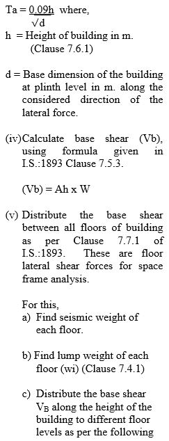
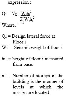
- Using details from STAAD Pro Model analysis the base shear can be worked out as follows :
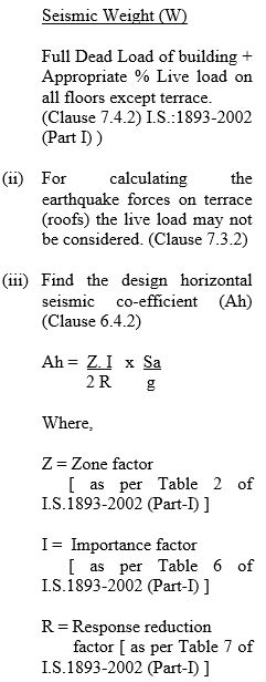
(i) Find seismic weight of the building; by taking sum of all reactions at footings level by considering full Dead load and Appropriate % of Imposed load as per Clause 7.3.1, Table 8 of I.S.:1893-2002 (Part I).
3. Seismic Analysis is carried out based on the following assumptions
(i) The Seismic Force acts, at a time along one direction only, i.e. when seismic force along with Dead and live load act on a space frame along X direction, then on Z direction only Dead and live load forces are acting and vise versa. Also, earthquake is not likely to occur simultaneously with wind or maximum flood or maximum sea weaves.
(ii) The nature of seismic force action is reversible in direction (i.e. + and – forces can act on the space frame)
(iii) Horizontal deflection of all joints of a frame, at particular floor level is same.
(iv) The individual space frame joint, shares the storey shear in proportion to its stiffness.
(v) The inverse of deflection of a joint is treated as a measure of its stiffness.
4. A judicious choice of beam sections (as explained in para 5) and column sections (as explained in para 6) will ensure deflection of the frames within permissible limits.
5. As per Clause 7.7.2, of I.S. 1893(Part-I):2002 to distribute horizontal lateral force to different lateral force resisting elements (joints), following procedure is done:
1) Find joint displacements of each joint by applying a unit horizontal fore say 5 KN or any Value in X & Z direction at each joint. (F element) and run the STAAD Pro Programme for load combination cases using partial load factor –1.
Generally the deflection in a frame at terrace level, is maximum.
As stated earlier the total base shear is shared in all X Z space frame joints of the building in inverse proportion of their deflections. The inverse of deflection for each space frame joint is calculated. Then using these values, ratio of (inverse of deflection of a particular frame joint (X/Z) Direction/sum of inverses of deflections of all (X/Z) Direction joint is worked out for each and every space frame joint. This value multiplied by the lateral force at that floor in a particular direction gives the Horizontal force to be applied at that joint in a particular direction.
6. After applying all horizontal seismic forces at all frame joints in X & Z direction, analysis is carried out for all required load combination cases and detailed space frame analysis results can be obtained.
All above calculations can be done by STAAD. Pro Programme output, using excel sheets.
For latest STAAD. Pro analysis programme, it is not necessary to calculate and apply seismic forces manually, but only by providing seismic parameters, STAAD Programme itself calculate and apply seismic forces both for static and dynamic analysis.
However, the designer should be alert to check the correctness of the seismic analysis done automatically by computer by verifying the result parameters like base shear, fundamental time period, Sa/g, seismic wt of building and deflections.
- WIND ANALYSIS:
- As per I.S.875:1987 (Part-V) & I.S.1893:2002 (Part-I), it is always an assumption that earthquake is not likely to occur simultaneously with wind or maximum flood or maximum sea weaves.
While designing, in the load combinations, dead load and imposed loads should be combined with either earthquake load or wind load.
There are various types of structures or their components such as some tall buildings, chimneys, towers, long span bridges etc. which require investigation of wind induced oscillations.
A large majority of structures met with in practice do not however, suffer wind induced oscillations, and do not require to be examined for dynamic effects of wind. These structures are to be analysed by static method.
- Static method of wind load estimation which implied a steady wind speed, has proved to be satisfactory for normal, short and heavy structures.
Analysis for wind forces by static approach is to be done as
per Clause 5 & 6 of I.S.875:1987 (Part III)
- Design wind speed is to be calculated …. Clause 5.3 of I.S.875:1987 (Part III) Vz = Vb K1 K2 K3
Where,
Vz = Design wind speed at any height Z in m/sec.
Vb – Basic wind speed .. Fig.1 or Appendix ‘A’ of I.S.875:1987 (Part III) map of wind speed to be attached.
K1– Probability factor .. C1 No.5.3.1 of I.S.875:1987 (Part III)
K2– Terrain, Height & Structure size factor .. C1 No.5.3.2 of I.S.875:1987 (Part III)
K3– Topography factor … Cl.No.5.3.3 of I.S.875:1987 (Part III).
- After calculating design wind speed (Vz), design wind pressure is to be calculated as per Cl.No.5.4 of I.S.875:1987 (Part III).
Pz = 0.6 Vz^2
Where,
Pz – design wind pressure in N/Sq.M. at height Z.
Vz – design wind velocity in m/s at height z.
- The wind load on a building shall be calculated for a) Building as a whole .. C1 No.6.3 of I.S. : 875:1987 (Part III)
F = Cf Ae Pd
Where, F = Force acting in a direction specified in respective tables given in I.S.: 875 (Part-3)1987
Cf – Force coefficient for the building .. Table 23 I.S.875:1987 (Part III)
Ae – Effective frontal area of the building Pd – Design wind pressure
b) Individual structure elements as roofs and walls or cladding units as per clause No.6.2.1 of I.S.875: 1987 (Part III).
F = (Cpe – Cpi) A Pd
Where,
Cpe– External pressure coefficient
Cpi – Internal pressure coefficient
A – Surface area of structure element or cladding unit
Pd – design wind pressure
- After calculating the wind force, static wind analysis is done on following assumptions similar for earthquake analysis:
(i) The wind force act at a time only along one direction i.e. when dead load, live load and wind forces are assumed to act on a frame along X direction then, along Z
direction only Dead and live load forces are acting and vice versa.
(ii) Horizontal deflection of all joints of frame at particular floor level, is same.
(iii) The individual frames share the storey horizontal force in proportion to it’s stiffness.
- Para 7.1 of the IS 875 (Part3):1987 stipulates that flexible slender structure and structural elements shall be investigated to ascertain the importance of wind induced oscillations or excitations along and across the direction of wind.
In general the following guide lines may be used for examining the problem of wind induced oscillations.
a) Building and closed structures with height to minimum lateral dimension ratio more than 5 and
b) Buildings and closed structures whose natural frequency in the first mode is less than 1 Hz.
Any structure or building which does not satisfy either of the above two criteria shall be examined for dynamic effects of wind. For the modal analysis (on similar lines of modal seismic analysis) will be carried out. If the wind induced oscillations are significant, analytical methods like use of wind tunnel modeling will have to be carried out.
- PREPARATION OF STAAD. PRO MODEL OF BUILDING.
- After study of Architectural drawings and field data and with the help of R.C.C. layouts, STAAD. Pro Building Model can be prepared. The computer programme has two methods of input data for preparing STAAD Pro Model.
a) Graphical Environment b) By analytical input of data.
Designer may use either of the above methods or combination of both to prepare space frame building model. Following steps are followed :
a) Analytical input of data :
1) Write joint co-ordinates of each joint by command “Joint Coordinates” create nodes.
2) These nodes are joined to each other to form a column, beam skeleton by command “Member incidences”.
The space frame Geometry is so formed.
3) Then column/beam sizes like width, depth are given by the computer programme command “Members property Indian”.
4) Material Information is given by command “Define Material”. The information like E (Modulus of elasticity of concrete), Poisson ratio, density, Alpha value, Damping value for R.C.C. are given.
5) “Constant” Command :
This command is used for fixing column orientations by “Beta angle”.
6) “Support” Command :
Supports (Fixed/Pinned) are given by this command.
7) “Member release” Command ;
Simply supported ends of beams are released for moments by this command.
8) “Members Offset” Command :
By this command position of beam always from column center is fixed.
By above Commands Building Geometry Model is prepared on STAAD Pro.
- LOADING :
STAAD. Pro Building Geometry so prepared is loaded by applying selfweight, wall loads, slab, lift loads, water tank loads etc. and Imposed loads, wind, seismic loads by creating different load cases. (Load 1, Load 2, Load 3 etc.)
- Load combination cases are prepared by use of above primary load cases by command “Load Combination”.
- Next command is “Perform analysis” and ”Load List”, last command is “FINISH”.
- ANALYSIS BY STAAD PRO
- Programme : Checking of Input data:
After preparation of STAAD Pro building Model, its input data shall be checked thoroughly by various commands available in STAAD Pro Software for its correctness.
- RUNNING OF STAAD.Pro ANALYSIS PROGRAMME :
By giving command “Perform Analysis” programme runs. And it gives results for the various Load Combination Cases provided to it.
2.1 Programme STAAD.Pro to give results for various load combinations with the appropriate load factors as per I.S.:456-2000 and I.S.1893:2002 (when so specified in input data) namely :
(1) 1.5 [Dead load + Live load]
(2) 1.2 [Dead load + Live load + Seismic load] for Seismic analysis.
(3) 1.5 [Dead load + Seismic load] for Seismic analysis.
(4) 1.2 [dead load + Live load + Wind load] for wind analysis.
(5) 1.5 [Dead load + Wind load] for wind analysis.
(6) 0.9 Dead load + 1.5 Seismic/Wind load for stability of the structure.
The designer has to decide which of these load combinations are required and accordingly give the details of horizontal loads.
2.2 Programme output gives values of axial force, moment and deflections for each member and R.C.C. Design of beams (i.e. area of reinforcement, details of shear reinforcement, columns, slabs, footings, shear walls etc.)
2.3 OUTPUT RESULTS FROM COMPUTER
The results obtained by running Programme STAAD. Pro should be thoroughly checked before accepting the same in the final design.
(A) The checking of input data is already discussed.
(B) Checking of displacements
(i) Displacement of joint are printed in meters. For fixed end of a frame the value of displacement must be zero.
(ii) At hinged end of a frame horizontal and vertical displacement must be zero.
(iii) The maximum horizontal displacement due to earthquake forces between successive floors shall not exceed 0.004 times the difference in levels between these floors.
(iv) Displacement of all joints on a particular floor should be equal.
(v) While checking of forces, at every joint following 3 equilibrium equations must be satisfied.
(a) Sum of all vertical forces must be zero.
(b) Sum of all horizontal forces must be zero.
(a) Sum of all moments at the joint must be zero.
Designer should personally check these points and check some joints for his own satisfaction.
- DESIGN OF VARIOUS R.C.C. ELEMENTS OF BUILDING
After the analysis is over, the designer will undertake the detailed design of various members of the building in the following order of actual construction, to be in tune with construction programme decided by the Field Engineers.
(i) Design of piles and pile caps/open footings (depending on the site and foundation conditions)
(ii) Design of columns.
(iii) Design of beams. (Plinth Level to Terrace Level)
(iv) Design of slabs. (Plinth Level to Terrace Level)
(v) Design of water tank/s.
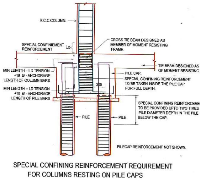
- DESIGN OF PILE AND PILE CAP
Piles are required to be provided where the strata of adequate bearing capacity is not available at reasonable depth, and site conditions dictate that open foundation is not feasible and economical. This is generally the case in black cotton soils and reclaimed areas.
For very low bearing capacity strata, and where pile foundation is not economical, we may adopt raft foundation. For codal provisions refer I.S.:2911.
It is a good design practice to provide minimum two piles or 3 piles in triangular pattern and generally not more than 4 piles (in square pattern) be provided under a column.
For piles, where the subsoil water is polluted and presence of sulfides and/chlorides is more than the safe limits, sacrificial cover shall have to be provided. However, the same shall be neglected while working out the area of concrete
required to sustain the load on pile. The diameter of pile and pattern of pile cap for twin or triple pile group shall be so chosen that the adjoining pile caps do not get overlapped and there is at least minimum distance between the two adjacent pile caps as stipulated in the code I.S.2911.
The mix of concrete considered for design shall be always one grade below than stipulated for casting.
- DESIGN OF OPEN FOOTINGS
2.1 ISOLATED FOOTINGS :
(i) Write down the reactions at various footing points for different Load combination.
(ii) The working load for each load combination is then worked out by dividing each load by the appropriate load factor of the particular load combination.
(iii)The maximum value of all these working loads is taken as design working load on footing.
(iv) The isolated footings are designed manually by using the design process as explained in HANDBOOK FOR R.C. MEMEBRS (Vol.II pages 359 to 380) OR any standard text book for R.C.C. Design.
(v) Normally trapezoidal footing is provided except where the site conditions demand otherwise.
(vi) Designer shall check that with the designed dimensions, the isolated footings are not getting overlapped. If they are getting overlapped, suitable combined footings shall be designed.
2.2 COMBINED FOOTINGS :
These are provided
(1) At the expansion joint locations and
(2) When it is noticed that the isolated footings, are getting overlapped or encroaching on adjoining property. The working load for combined footing shall be sum of working loads of columns constituting the combined footing. For manual analysis and design of combined footing, refer any standard textbook.
- SPECIAL TYPES OF FOOTINGS :
For design of pedestal or any other special type of footing like strip footing etc., refer standard text books.
- DESIGN CHECKS FOR ALL TYPES OF FOOTINGS :
The design shall be checked for following :
(1) Check for single shear, double shear.
(2) Check for negative moment (if active) (3) Check for bearing pressure on top of footing.
- DESIGN OF COLUMN SECTION :
5.1 A column is subjected to direct load and moments across its axes. Find out design loads and design
moments across appropriate axes from the output of relevant X direction and Z direction frame analysis, for the design section under consideration in STAAD Pro software analysis.
The column design by Limit State Method for reinforced concrete structures shall be as per following load combinations : (I.S.1893 Part I :2002, CL.6.3.1.2)
1) 1.5 (DL + IL), 2) 1.2 (DL + IL + EL), 3) 1.5 (DL + EL), 4) 0.9 DL + 1.5 EL
Similar combinations will be applicable in case of wind analysis i.e. replacing seismic forces by wind forces.
The columns shall be designed as uniaxial or biaxial depending upon whether the moments are acting across one or both axes of column and their relative magnitudes.
Effective length of column member shall be worked out considering end conditions and used in the calculations. (I.S.456:2000, Table 28, Cl.E-3)
The design of column given by STAAD-Pro programme may be verified for its adequacy OR otherwise the column design is done manually as per “HANDBOOK FOR DESIGN R.C. MEMBERS” (Limit State Method) Vol.II as explained in pages to for uniaxial columns and for biaxial columns pages 322 to 337 and for circular columns pages 342. Computer programme “ASP2” is also available.
The design section and the reinforcement shall satisfy all the combinations stated above. 5.2 APPROACH FOR ECONOMIC DESIGN OF COLUMN :
In the design of a column, two factors are to be keenly watched namely pu/fckbd and interaction factor.
The pu/fckbd factor is a measure of compressive force in column and by keeping the value of this factor is equal to or less than 0.4, it is seen that the concrete section provided is utilised to the maximum extent.
The interaction factor is a measure of degree of utilisation of steel reinforcement provided in the column section. The value of this factor (calculated as per clause 39.6 of I.S.456) as close to 1.00 ensures that the external loads and moments are resisted optimally by the proposed concrete section along with the (proposed) steel reinforcement pattern.
5.3 Always begin by designing the top most section of a column and then proceeding successively to the lower section.
5.4 Begin the design by choosing “one bar at each corner” i.e. 4 bar pattern (giving total area of reinforcement required on the basis of minimum steel criteria) and if this first approximation is not safe then modify the diameter of bars and/or reinforcement pattern till you get the interaction Ratio as close to 1.0.
As far as possible for the next lower story column section, continue the same bar diameters and reinforcement pattern.
5.5 CHOOSING PROPER REINFORCEMENT PATTERN
While deciding the pattern it should born in mind that when the C.G. of the steel provided is away from the N.A., it gives higher moment of resistance to the section.
5.6 If the first approximation of steel reinforcement proves inadequate, try to increase the diameter and/number of bars. It shall be ensured that in the pattern selected, the bigger diameter bars are always placed near the corner/faces away from axis of bending. Each successive trial shall be taken by gradually changing reinforcement, and the final trial should provide just adequate steel reinforcement. The reinforcement pattern should fulfill the minimum spacing criteria. The reinforcement bars are required to be laterally tied by providing links of proper shape. 5.7 While choosing the reinforcement pattern, provide adequate number of bars so that it satisfies spacing criteria as per I.S.456, Cl.26.5.3.1 and Cl.26.5.3.2.
5.8 A sketch giving the suitable link arrangements for column reinforcement which will create least congestion and aid easy flow of concrete in the steel cage is kept at page number 59 for guidance.
5.9 The number of reinforcement bars shall be so chosen that for uniaxial column, equal area of steel on opposite faces is provided and for biaxial column, equal area area of steel on opposite faces is provided.
5.10 For requirements of ductility detailing refer para 6.6 . (Page 35)
- DESIGN OF BEAMS :
(i) The computer output of STAAD.Pro gives the area of required steel at supports, at quarter span (from each end) and at centre of span. The Designer has only to choose the diameter and numbers of top and bottom bars such that actual steel area is just more than the design value and there is no congestion of steel.
Non congestion can be ensured by keeping horizontal distance between the bars as the greatest of the following :
(a) The diameter of bar (in mm) if the diameters are Equal.
(b) The maximum diameter (in mm) of bar if the diameters are Unequal.
(c) 5 mm. more than the nominal maximum size of coarse aggregate.
For ensuring better compaction of concrete with needle vibrator, it is desirable that this minimum clear distance be 50 mm.
(ii) The anchor bars (at top and bottom) shall be minimum 2 Nos.
(iii) Where it is not possible to accommodate all the bars in one layer, provide them in layers. The vertical distance between these layers shall not be less than the greatest of following :
(a) 15 mm. (b) 2/3 of the nominal maximum size (in mm) of coarse aggregate.
(c) Nominal size of bars (in mm.)
(iv) As per Designs Circle’s practice bars at the bottom of beam are taken straight without bending.
(v) When there are collinear beams over a support the extra steel over the support (at top and/bottom as the case may be) shall be maximum required for the either of the two.
For collinear beams the extra steel over support shall be continued in the adjoining span for a length equal to anchorage length or 25 % of the adjoining span whichever is more.
For non collinear beams the extra steel over support shall be anchored in supporting column for full anchorage length.
(vi) The stirrups of shear reinforcement shall be provided with appropriate diameter of H.Y.S.D. bars so that there is no congestion of reinforcement in beam and it shall be seen that the ductility criteria where applicable is also fulfilled.
6.1 For requirements of ductility detailing refer para 6.6 (page 35)
- DESIGN OF SLABS :
(i) The slabs may be one way or two way depending on the panel dimensions. The design moment coefficients of a particular slab shall be taken in accordance with its boundary conditions.
(ii) Design of slabs is done manually by referring to “Handbook for R.C.C.” Members (Limit State Method) Vol. I or any standard textbook. (iii) As per Designs Circle’s practice minimum diameter of bars for slabs shall be 8 mm.
(iv) In case of future vertical expansion, the R.C.C. layout of the top floor shall be as per Architect’s plan. However, the slab reinforcement shall be maximum of that required for future floor or present terrace.
7.1 DESIGN OF OVERHEAD WATER TANK/S
The design of water tank is carried out as per procedure given in the “Reinforced Concrete Designer’s Hand Book” by Reynolds, and conforming to I.S.:3370.
- COMPUTER AIDED DESIGN USING IN HOUSE DEVELOPED SOFTWARE
With the availability of high speed and large memory capacity desk top computers in Designs Circle, much of the analysis is now carried out on these computers.
Following is the list of computer programmes available in Designs Circle with User’s Manual :
- “FOOT” : This programme designs isolated footing as per limit state method of design. Column size, concrete mix, safe bearing capacity of the founding strata and working load on the column are the basic inputs. All the checks as per code are included in the programme.
- “EC FOOT” : This Programme designs combined footing along the expansion joint. Column details alongwith their orientation expansion joint details etc. are basic inputs. All
the checks as per code are included.
- “SLAB” : This Programme designs one way and two way slabs as per “Limit State Method” design. The basic data is concrete mix, span/s, clear cover to reinforcement bars, slab loading and end conditions.
- “ASP2” : The basic input required to run this programme are section dimensions, unsupported length and effective length in both X and Y direction, reinforcement pattern and different load combinations.
The main limitation of this programme is that it is workable only with rectangular and square column section.
This Programme designs for given column section, reinforcement pattern and, load combination and checks the adequacy of section. For this programme the X axis is always assumed to be along the smaller dimension of column. The programme output gives the results for the chosen column section and reinforcement pattern the values of [Pu/(fck x b x d)] and Interaction Factor Values for each load combination case under consideration.
- EARTHQUAKE RESISTANT DESIGN GUIDELINES AS PER I.S.:4326
- The Seismic Design Philosophy is to accept damage to a building during a earthquake. Hence the I.S.:1893 code specifies design seismic force for a building, only a fraction of the seismic force that it will experience if it were to remain Linear elastic during severe ground motions. Thus the structure in severe seismic zones should be necessarily ductile.
- Meaning there by that the members of reinforced concrete shall be under reinforced so as to cause a tension failure. Also it should be so designed that the premature failure due to shear or bond may not occur subject to the provisions of I.S.:456-1978. Ductile failure will enable structure to absorb energy during earthquake to avoid sudden collapse of structure.
- I.S.:4326-1993 deals with earthquake resistant design and construction of design. Some important clauses are as under :
Clause 4.4 Building Configuration
4.4.0 In order to minimize torsion and stress concentration, provisions given in 4.4.1 to 4.4.3 should be complied with as relevant.
4.4.1 The building should have a simple rectangular plan and be symmetrical both with respect to mass and rigidity so that the centers of mass and rigidity of the building coincide with each other in which case no separation sections other than expansion joints are necessary. For provision of expansion joints reference may be made to I.S.:3414-1968.
4.4.2 If symmetry of the structure is not possible in plan, elevation or mass, provision shall be made for torsional and other effects due to earthquake forces in the structural design or the parts of different rigidities may be separated through crumple sections. The length of such building between separation
sections shall not preferably exceed three times the width.
4.4.3 Buildings having plans with shapes like, L, T, E and Y shall preferably be separated into rectangular parts by providing separation sections at appropriate places.
Note 1.
The buildings with small lengths of projections forming L, T, E or Y shapes need not be provided with separation section. In such cases the length of the projection may not exceed 15 to 20 percent of the total dimension of the building in the direction of the projection.
Note 2.
For buildings with minor asymmetry in plan and elevation, separation sections may be omitted.
Clause 4.5 Strength in Various Directions
The structure shall be designed to have adequate strength against earthquake effects along both the horizontal axes. The design shall also be safe considering the reversible nature of earthquake forces.
Clause 4.6 Foundations
The structure shall not be founded on such loose soils which will subside or liquefy during an earthquake, resulting in large differential settlements.
Clause 4.7 Ductility
The main structural elements and their connection shall be designed not to have a ductile failure. This will enable the structure to absorb energy during earthquakes to avoid sudden collapse of the structure. Providing reinforcing steel in masonry at critical sections, as provided in this standard will not only increase strength and stability but also ductility.
Clause 5 Special Construction Features
Clause 5.1 Separation of Adjoining Structures.
Separation of adjoining structures or parts of the same structure is required for structures having different total heights or storey heights and different dynamic characteristics. This is to avoid collision during an earthquake. Minimum total gap shall be 25 mm.
Clause 5.2 Separation or Crumple Section.
5.21 In case of framed construction, members shall be duplicated on either side of the separation or crumple section. As an alternative, in certain cases, such duplication may not be provided, it the portions on either side can act as cantilevers to take the weight of the building and other relevant loads.
- DUCTILE DETAILING AS PER 13920:1993.
I.S.:4326, The Code of Practice for earthquake resistant design and construction of Building, while commenting on certain special features for the design and construction of earthquake resistant buildings, included some details for achieving ductility in reinforced concrete buildings.
The I.S.:13920 has taken note of latest developments, experiences gained from the performance of structures which were designed and detailed as per I.S.4326, during the recent earthquakes. It covers provisions for earthquake resistant design and detailing of reinforced concrete structures in particular. (As such it includes provisions of I.S.:4326 also). Now all ductility detailing shall comply I.S.:13920.
Some important clauses of this code are as follows :
Clause 1.1.1
Provisions of this code shall be adopted in all monolithic reinforced concrete structures located in Seismic Zone III, IV & V.
Clause 5.2 For all buildings which are more than 3 storeys in height the minimum grade of concrete shall be M 20.
Clause 5.3
Steel reinforcement of grade Fe 415 or less only shall be used.
Clause 6 : For flexural members
6.1.1 The factored axial stress on the member under earthquake loading shall not exceed 0.1 fck.
6.1.2 The member shall have a width to depth ratio of more than 0.3.
6.1.3 Width of flexural member not less than 200 mm.
6.1.4 Depth of member not more than 0.25 of the clear span.
Clause 6.2 : Longitudinal Reinforcement : 6.2.1 (a) At least two bars at top and two bars at bottom shall be provided throughout the member length.
(b) The tension steel ratio on any face at any section shall not be less than е (min) 0.24 [(square root of fck)/fy]
6.2.2 The maximum steel ratio on any face at any section shall not exceed е (max)=0.025.
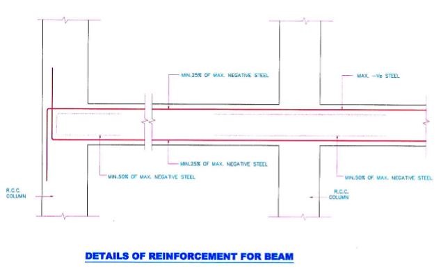
6.2.3 The positive steel at a joint face must be at least equal to half the negative steel at that face.
6.2.4 The steel provided at each of the top and bottom face of the member at any section along its length shall be at least equal to one fourth of the maximum negative moment steel provided at the face of either joint.
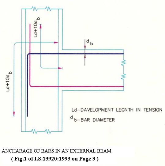
6.2.5 In an external joint both the top and bottom bars of the beam shall be provided with anchorage length beyond the inner face of column equal to development length in tension plus 10 times the bar diameter minus the allowance for 90 degree bend(s).
In an internal joint, both face bars of the beam shall be taken continuously through the column.
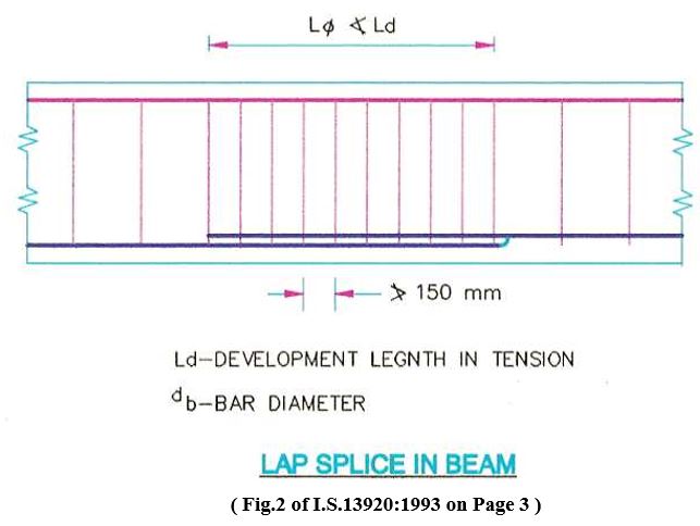
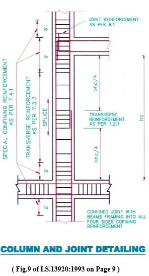
6.2.6 The longitudinal bars shall be spliced, only if hoops are provided over the entire splice length at a spacing not exceeding 150 mm.
The lap length shall not be less than the development length in tension.
Lap splices shall not provided
(a) within a joint
(b) within a distance of 2d from joint face and
(c) within a quarter length of member where flexural yielding may generally occur under the effect of earthquake forces.
Not more than 50 percent of bars shall be spliced at one section.
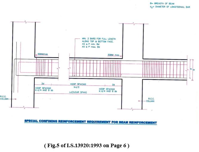
6.3.5 The spacing of hoops over a length of 2d at either end of a beam shall not exceed.
(a) d/4 and (b) 8 x diameter of smallest bar
But not less than 100 mm.
The first hoop shall be at a distance not exceeding 50 mm. from the joint face. Vertical hoops at the same spacing as above shall also be provided over a length equal to 2d on either side of a section where flexural yielding may occur under the effect of seismic forces.
Elsewhere the beam shall have vertical hoops at a spacing not exceeding d/2.
Clause 7: Columns subjected to bending and axial load.
7.1.1 These requirements apply to columns which have factored axial force in excess of (0.1 fck) under the effect of earthquake forces.
7.1.2 The minimum dimension of column shall be 200 mm. However where in frames where beams have c/c span exceeding 5 m, or column having unsupported length exceeds 4 m. the shortest dimension shall not be less than 300 mm. 7.1.3 The ratio of shortest dimension to the perpendicular dimension shall be preferably NOT less than 0.4.
Clause 7.2 : Longitudinal Reinforcement
7.2.1 Lap splices shall be provided only in the central half of the member length. It should be proportioned as a tension splice. Hoops hall be provided over the entire splice length at spacing not exceeding 150 mm. center to center.
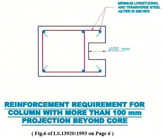
Not more than 50 percent of bars shall be spliced at one section. 7.2.2 Any area of a column that extends more than 100 mm. beyond the confined core due to Architectural requirements shall be detailed in the matter.
In case the contribution of the area to strength has been considered then it will have the minimum longitudinal and transverse reinforcement as per this code.
However if this area has been treated as non structural the minimum reinforcement shall be governed by I.S.456 provisions.
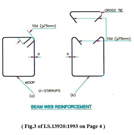
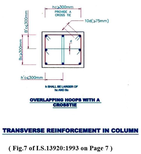
Clause 7.3 : Transverse Reinforcement
7.3.2 The spacing of rectangular hoops shall not be more than 300 mm c/c. If the length of any side of stirrup, exceeds 300 mm a cross tie shall be provided or a pair of
overlapping hoops may be provided.
Clause 7.4 : Special Confining Reinforcement
7.4.1 This shall be provided over a length of (lo) from each joint face towards mid span on either side of any section lo shall not be less than
(a) larger lateral dimension of the member
(b) 1/6 of clear span of the member and
(c) 450 mm.
7.4.2 When a column terminates into a footing or mat special confining reinforcement shall extend at least 300 mm into the footing or mat. 7.4.6 The spacing of hoops used as a special confining reinforcement shall not exceed 1/4 of minimum member dimension but need not be less than 75 mm nor more than 100 mm.
7.4.7 The minimum area of cross section of bar forming circular hoop or spiral to be used as special confining reinforcement shall not be less than
Ash = 0.09 S Dk (fck/fy) [(Ag /Ak -1.0 ] fy Where
Ash = area of the bar cross section
S = Pitch of spiral or spacing of hoops
Dk = diameter of core measured to the outside of spiral or hoop
fck = characteristic compressive strength of concrete cube. fy = yield stress of (spiral/hoop) steel Ag = gross area of column cross section Ak = area of concrete core should not exceed 300 mm (see figure 7)
7.4.8 The area of cross section Ash of the bar forming rectangular hoop to be used as special confining reinforcement shall not be less than
Ash = 0.18 Sh.fck [(Ag / Ak -1.0 ] fy Where
h = longer dimension of rectangular hoop.
Ak = Area of concrete core in the rectangular hoop measured to its outside dimensions.
Clause 8 : Joints of frames :
8.1 The special confining reinforcement as required at the end of column shall be provided through the joint as well, unless the joint is confined as specified by 8.2.
8.2 A joint which has beams framing into all vertical faces of it and where each beam width is at least 3/4 of the column width, may be provided with half the special confining reinforcement required at the end of column. The spacing of hoops shall not exceed 150 mm.
CHAPTER-V
DETAILING
- NOTES TO APPEAR ON VARIOUS SCHEDULES
[A] GENERAL (Applicable for all schedules) :
1. For general instructions and detailing of reinforcement, refer to SP-34 of bureau of Indian Standards I.S.13920 and sketches in this chapter.
2. Unless otherwise specified in the respective schedules, the minimum concrete mix shall be M 20 (characteristic strength 20 N/sq.mm.) and grade of concrete depending on exposure condition as per Clause No.8.2.2 and Table No.5 of I.S.456:2000.
3. Reinforcement shall be high yield strength deformed bars (Fe 415) conforming to I.S.:1986 with latest amendments.
4. Any deviations from designed sizes, found necessary on site shall be got approved well in advance before execution from Superintending Engineer.
5. Development length of reinforcing bars shall be in accordance with Clause 26.2.1 of I.S.456:2000.
6. Approval to R.C.C. layouts and to the sizes of columns and beams above plinth level shall be obtained from Architect prior to the execution.
7. For notation of slabs, beams and columns and column orientation refer to R.C.C. layouts of respective floors.
8. For all R.C.C. elements minimum cover shall be provided depending on condition of exposure described in 8.2.3 shall be as per Table 16 of I.S.456:2000 (Clause 26.4.2) and nominal cover to meet specified period of fire resistance shall be as per Table 16A of I.S.456: 2000, Clause No.26.4.3.
[B] R.C.C. LAYOUTS :
1. This R.C.C. layout is based on the Architect’s Drawing No…. Job No. , Dated. ….. .
2. R.C.C. layout at a particular level indicates (i) beams and slabs at that level, (ii) supporting columns below that level and (iii) walls above that level.
3. Any discrepancies noticed between these layouts and Architect’s drawings shall be communicated to office of ……. (where designs are prepared) for clarification before starting execution.
4. Any change in the location of beams, orientation of column/s other than that shown in the layouts, shall be got approved in advance from Superintending Engineer. [C] FOOTINGS/PILES AND PILE CAPS :
1. For column numbers and their orientation refer to R.C.C. layout at plinth level drawing No……./……. .
2. The difference in levels between adjoining footings shall not exceed than that permitted vide Clause No.9.7 of I.S.:1904. 3. The larger dimension of a footing shall be oriented along the longer side of a column, unless the sketch indicates the contrary.
4. Reinforcement parallel to breadth of footing shall be laid first.
5. Reinforcing bars shall be bent up at the edges of footings to get required development length.
6. The sub-soil and sub-soil water are assumed to be free from harmful elements.
7. Footings/pile and pile caps are designed for (ground + –) (number of stories for which footings are designed).
8. Footings are designed for safe bearing capacity of —- t/sq.m.
9. For details of dowel bars and their arrangement refer to schedule of columns from footing to plinth level Drawing No…./… .
[D] COLUMNS :
1. For orientation of columns refer R.C.C. layout at plinth Drawing No….. /….. .
2. Reduction in column size shall be effected from the top of the slab at relevant floor level.
3. For any change proposed at site, in the size of column section and/or their orientation, approval of Superintending Engineer shall be obtained before execution.
4. Larger diameter bars shall be provided at corners, unless otherwise indicated in the sketch.
5. Arrangement of binders shown in the sketch is suggestive, any other alternative arrangement in accordance with the relevant provisions in I.S.:456 and I.S.:2502 may be adopted.
[E] BEAMS :
1. For notation of beams refer R.C.C. layout at …… floor level Drawing No……. / …… .
2. In case of collinear beams, top reinforcement over a support for non-seismic region and both top and bottom reinforcement at a support for seismic region shall be continued in adjacent span for full development length or span/4 of adjoining span whichever is more.
3. In case of collinear beam and in case there is no beam on the other side, the top reinforcement over a support for non-coastal region and both top and bottom reinforcement at a support for coastal region shall be anchored in the supporting column for full development length. In case of grid beams it shall be anchored in the supporting beams and columns.
4. Minimum and maximum distance between individual bars shall be as per Clause No.26.3 of I.S.456:2000 with latest amendments.
5. The end of a beam except in a grid not having either a column support or a collinear beam shall be considered to be a discontinuous end. The top and bottom reinforcement at such a discontinuous end shall be terminated in the supporting beams instead of anchoring for full development length.
6. In case diameter and number of bars of adjacent collinear beams are same then these bars shall be kept continuous.
7. If the spacing of stirrups in any region of a beam (such as 0 to D, D to 2d, etc. is not a submultiple of the depth of the beam, then the same spacing shall be continued in the next region for one more spacing before starting the new spacing to be provided in the next region.
8. Extra steel at top of support between adjacent beams is shown in any one beam. This extra steel is to be continued on both sides of the support for required anchorage length or span/4 of respective beam, whichever is more.
9. Top of internal plinth beams shall be 15 cms. below plinth level and top of external plinth beams shall be 15 cms. below ground level.
10. Beams at toilet portion shall be cast 20 cm. below general floor level.
11. Necessary provision for reinforcement of chajja, facias, canopy, fins, pardi and brackets etc. shall be made while casting of relevant beams.
[F] SLABS :
1. For notation of slabs refer R.C.C. layout at ……floor level Drawing No……. / ……. .
2. Slabs of toilet portion shall be cast at 20 cm. below general floor level.
3. Reinforcement in chajjas shall be provided as per the sketch No.4A of Designs Circle’s Technical Note No.7502.
4. In slab notation, the first figure indicate the imposed live load assumed in design. It shall be ensured by the field engineers that the actual live load on the slab does not exceed this specified load.
[G] WATER TANK :
1. Mix of the concrete for water tank shall be M 20.
2. All dimensions are in cms, unless otherwise specifically mentioned.
3. Plans and sections are not to scale.
4. Necessary water proofing treatment, load of which shall not exceed 100 kg/sq.m. shall be given to the tank. 5. The drawing shows only structural details Air vents, over flow pipes, inlets, outlets, scour pipes, man holes etc. have not been shown on the drawing.
6. Manholes of adequate diameter shall be provided as per requirement/s with extra trimmer bars below main reinforcement of slab as shown in the drawing.
7. The horizontal and vertical bars of the walls shall be continued
beyond the bend for full development length.
8. The diameter and position of over flow pipe shall be such that it will ensure a free board of 15 cms.
9. Column reinforcement shall be continued upto top of bottom slab of water tank.
10. R.C.C. Tank/s of ….. Litres capacity shall rest on columns Nos…., …, …, …, …, and …
- VARIOUS FORMAT
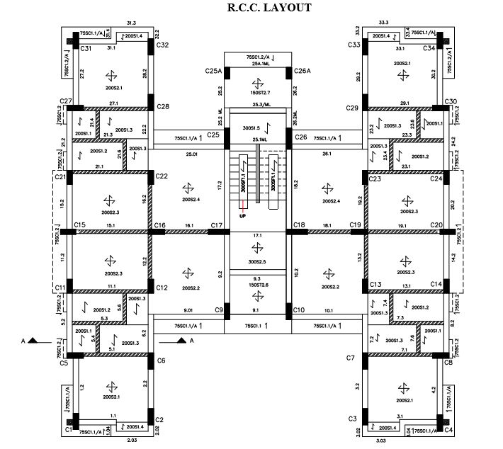
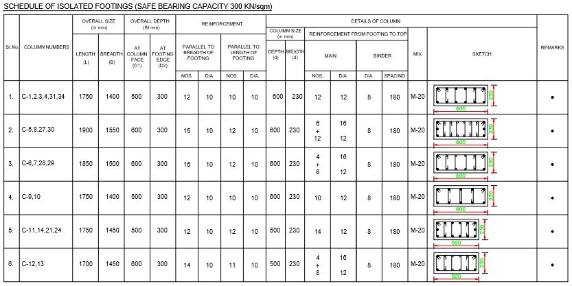
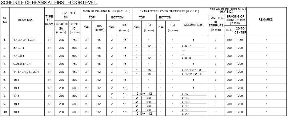
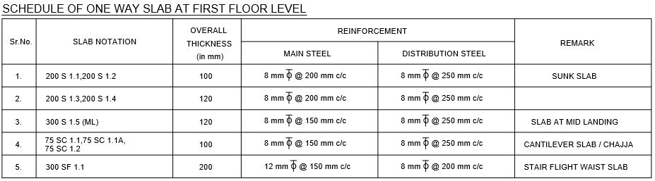
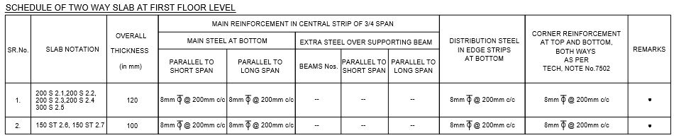
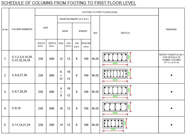
- FIELD DATA PROFORMA STANDARD PROFORMA FOR FURNISHING FIELD DATA FOR COMMENCING DESIGN OF BUILDING PROJECTS
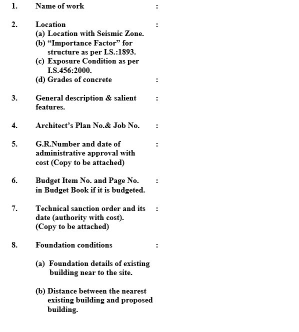

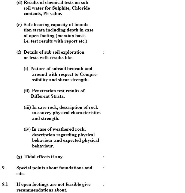
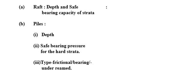
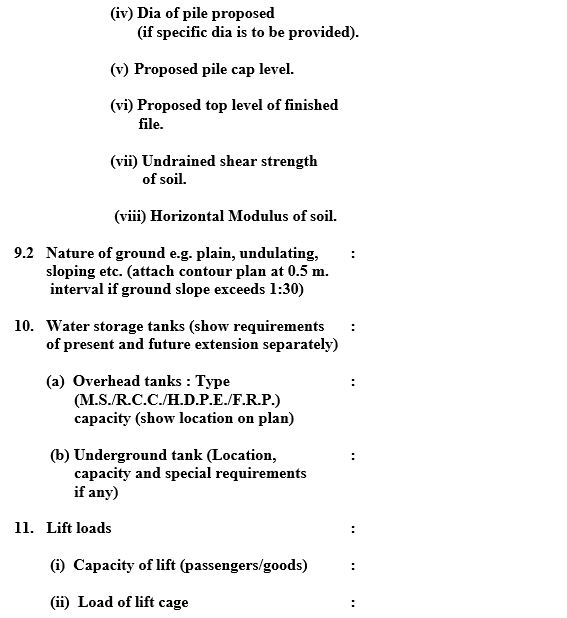
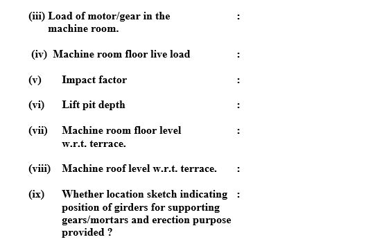
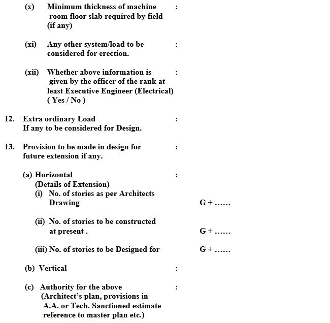
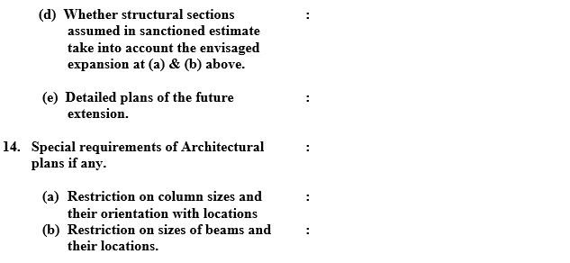
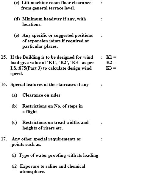
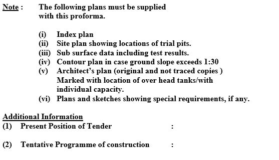
- SKETCHES