
Setting up the instrument
The aim of this tutorial is to guide you through the procedures for setting up a tripod to make it ready for use.
Parts of the tripod

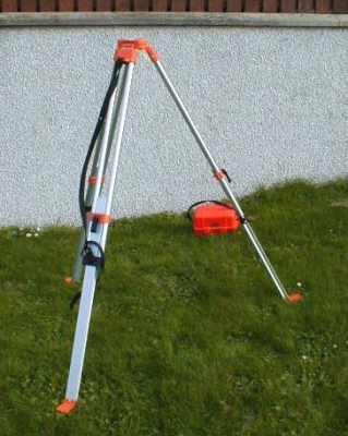
Basic Kit, tripod and instrument in carrying case
Each leg of a tripod is adjustable for length. The legs are locked by a lever clamp (left) or screw (right).
Once the legs have been set to the correct length it is important that the locking lever or screw is tight. Otherwise, the leg may move in use which means the instrument will have to be set up again, and all readings taken again as the instrument height will have changed.

Level in transit case. Note the plumb bob (lower left) which may be used to centre the instrument over a survey station.

Setting up the tripod
Aim – to set up the tripod so that it is secure, the head is approximately level, the instrument telescope will be at eye level, you will be able to see the staff through the telescope
- Using a methodical approach keeps the task simple.
- Undo carrying straps
- Extend legs
- Set tripod in position – if the ground is sloping place two legs on the downhill side
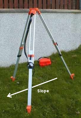
- Firmly press the two tripod feet on the downhill side into the ground using your own foot on the tripod’s foot plate. (This will tilt the head)
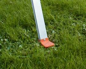
Foot plate on tripod leg
-
Move the third leg so that the head looks level and the instrument telescope will be at a comfortable height when this leg is firmly pushed into the ground.
-
Fine adjustments can be made by changing the length of each leg.
-
Make sure that the clamp or locking screw is tight when finished.
Notes:
If the tripod head is not almost level you may have difficulty setting up the instrument.
Do not lean on the tripod when using it, as this could disturb the setting of the instrument.
-
Tripod set up, legs secure, head level at a suitable height for use, ready for the instrument.
Attaching the Instrument
The aim of this tutorial is to show you how to attach the level to the tripod. The attachment method is the same for most modern survey instruments including levels, theodolites, and EDM systems.
Attaching the instrument to the tripod
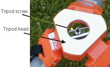
Tripod Head has a polished level surface for the instrument to stand on. Some tripods have a cover to protect the head when not being used. Take care not to damage the surface.
The Tripod Screw is captive and mounted on a movable bracket to allow the instrument to be centred over a station if necessary.
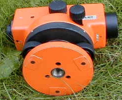
The instrument base plate (trivet stage) is threaded to take the tripod screw. The three raised ‘feet’ are machined to give a stable contact with the tripod head.
The tripod screw has a large head and is designed to be tightened and undone by hand. Do not apply undue force.
Parts of the Instrument and Levelling Head
The aim of this tutorial is to introduce you to the automatic level and levelling head on the instrument. The three screw levelling head is found on most modern survey instruments including levels, theodolites, and EDM systems.
Typical parts of an automatic level
- The instrument is secured to the tripod head using the tripod screw.
Right side of Level
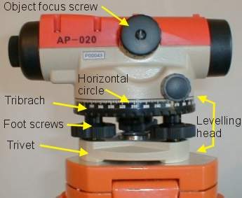
The levelling head has three parts:
- A top plate or tribrach which carries a spirit level and the instrument
- Three levelling, or foot, screws
- A foot plate or trivet that attaches to the tripod head
Also labeled in this picture:
- The horizontal circle, which allows the instrument to be used to measure horizontal angles to an accuracy of 1° (Not found on all instruments)
- The object focusing screw, which is used to bring the staff or other image in to focus.
Top of Level
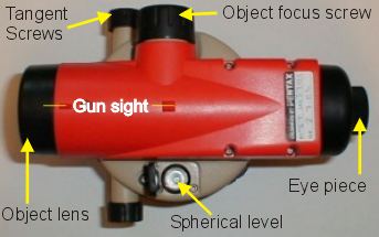
This picture shows the instrument controls:
- Spherical level is a bubble spirit level attached to the tribrach and referenced to the axis of the telescope. In use the bubble must be within the circle for the instrument to give a horizontal sight line (Collimation).
- The eye piece is adjustable and should be set for each observer to bring the cross hairs in to sharp focus.
- The instrument can be rotated by hand, using the ‘gun sight’ on top of the telescope to find the staff.
- Tangent screws (one on each side) allow fine adjustment when aligning the telescope on the staff, or setting out a horizontal angle using the horizontal circle.
- The Telescope is focussed using the object focus screw on the right side of the instrument.
Left side of level
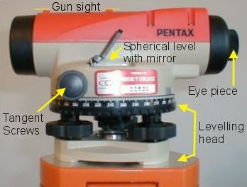
The only new component in this view is the mirror over the spherical level. This mirror allows the observer to see the bubble and confirm that the instrument is correctly levelled before taking a reading. Not all instruments will have a mirror.
Linear bubble level

Not all instruments have exactly the same features. This automatic level has a linear bubble level. It only has one tangent screw and the horizontal circle is replaced by marks at 90° intervals to allow setting out of right angles.
Eye piece focusing of the cross hairs and an object focus screw are usually provided on all instruments.
Adjusting the levelling head
Aim – To level the tribrach so that the telescope rotates in a horizontal plane.
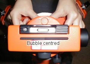
Levelling an instrument with a linear bubble tube.
- Align the bubble tube parallel to two foot screws.
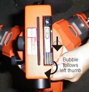
- Facing the instrument rotate both foot screws in opposite directions at the same time. Either thumbs moving inwards or thumbs moving outwards.

- The bubble moves in the direction of the left thumb.
- When the bubble has settled in the exact centre of the tube the instrument is level on this axis.
- Rotate the telescope through 90° so the bubble tube is aligned with the third levelling screw.
- The first two screws are level so they must not be touched.
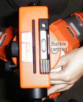
- Using the left hand adjust the third levelling screw to centre the bubble. Again the bubble will move in the same direction as the left thumb.
- With the bubble centred the instrument should be level.
- As a check rotate the instrument through 90°. If necessary re-level the original two foot screws and repeat the rotation to check the third one.
- You may have to do two sets of adjustments before the instrument is level and the bubble remains in the centre of the tube as the telescope is rotated.
- The tube is engraved with calibration marks to show the centre. The bubble must be no more than one space on the calibration scale off the centre for the compensator to work.
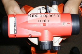
Levelling an instrument with a spherical spirit level.
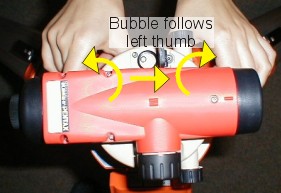
- Align the telescope parallel to two foot screws.
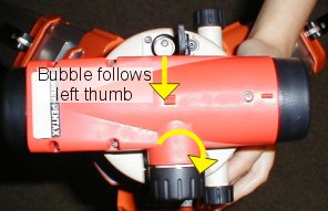
- Facing the instrument rotate both foot screws in opposite directions at the same time. Either thumbs moving inwards or thumbs moving outwards.
- The bubble moves in the direction of the left thumb.
- When the bubble has settled opposite the centre mark the instrument is level on this axis.
- The bubble will probably be against the side of the circular spirit level, and needs moving in to the centre.
- The first two screws are level so they must not be touched.
- Using the left hand adjust the third leveling screw to centre the bubble. Again the bubble will move in the same direction as the left thumb.
- With the bubble centred the instrument should be level.
- As a check rotate the instrument through 90°. If necessary re-level the original two foot screws and repeat the rotation to check the third one.
- The tube is engraved with a calibration circle to show the centre. The bubble must remain within this circle for the compensator to work.

Principle of the Automatic Level
The aim of this tutorial is to describe the basic principle of an automatic level.
Principle of levelling.
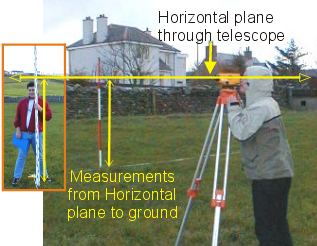
- The level is an optical instrument that provides a height reference. This reference is a horizontal plane through the axis of the telescope, known as the “Height of Collimation”.
- Once the height of collimation (or instrument height) has been measured the height of other stations can be found by measuring from this plane with a staff.
- The height of collimation is found by taking a backsight to a staff placed on a bench mark. The staff reading is added to the bench mark value to obtain the height of collimation.
- Once the height of collimation has been found ground height at any spot below this plane can be found by observing the staff and subtracting the staff reading from the height of collimation.
Principle of the Automatic Level
The aim of this tutorial is to describe the basic principle of an automatic level.
The Automatic Level

- It is essential that the sight line through the telescope is exactly horizontal. If not errors will occur. One solution to this problem is the automatic level.
- The automatic level has a compensator mechanism that uses a combination of fixed prisms or mirrors and a moving prism suspended on a pendulum to give a horizontal reference. When correctly set up the compensator will ensure that the ray of light through the centre of the reticule is exactly horizontal.
- Design of the compensator mechanism varies with each manufacturer, so the diagram above is intended to show the principle of the method, not a specific instrument.
- Not shown in the diagram is a damping mechanism to stop the pendulum from continuing to swing when the instrument moves. The quality of the damping mechanism is very important; too little damping will give an unsteady image which may blur in windy conditions, but too much damping may lead to errors if the pendulum does not respond to slight movements of the instrument.
- The reticule is a glass plate with fine cross hairs engraved to provide the height reference. The eye piece should be adjusted to bring the reticule into sharp focus. The internal focussing lens is then controlled by the focussing screw on the side of the instrument to bring the staff image in to focus on the reticule.
Staff and its graduation
Levelling staff.

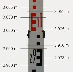
- Two “E” pattern staffs are shown on the right, note slight differences in the marking and numbers. The “E” pattern is designed to make it easy to read a small section of the scale when seen through a telescope.
- The staff is simply a large ruler, available in lengths of 3, 4 or 5 metres and usually made of aluminium with telescopic sections.
- The sections have locking buttons to ensure accurate length is maintained.
- Some staffs also have an extended length scale in mm on the back.
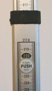
- Measurements are in metres and cm (10mm blocks) which enable heights to be estimated to 1 mm. Alternating colours are used to differentiate each metre length, the most common being black and red on a white background.
- Major graduations occur at 100 mm intervals and are denoted by figures. Minor graduations are at 10 mm intervals and form coloured squares or intervening spaces. The lower 50 mm of any 100 mm block are joined by a band to form the distinctive E pattern which is designed to make reading a small section of the staff in the telescope easier.
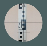
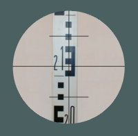
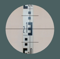
- Example staff readings are shown below:
Through the telescope

Focus the reticule.
- The reticule (or diaphragm) is a glass plate with fine lines etched on it to provide the horizontal reference and stadia marks for estimating distance. When first looking through the telescope rotate the eye piece to bring the reticule in to sharp focus.
- Each observer will need to focus the reticule to allow for their own eye.
- Failure to do so will cause parallax, where a small movement of the eye’s position will cause the horizontal lines to give a different staff reading.
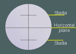
- With the eye piece focused you will see a vertical and a horizontal line dividing the field of view. The middle horizontal line marks the horizontal plane through the telescope (height of collimation) and is the reference for all height readings.
- There may also be two short stadia lines. Stadia are used for measuring the distance to the staff by multiplying the difference between the two stadia readings by a constant (usually 100).
Focus on the staff
- Align the telescope on the staff using the gun sight on the top of the instrument and gently rotating the telescope by hand.
- Using the side focussing screw bring the staff in to sharp focus.
- Fine adjustment of the alignment can be made with the tangent screw.
- Check that the spirit level bubble is within the central portion of the scale before reading the staff.
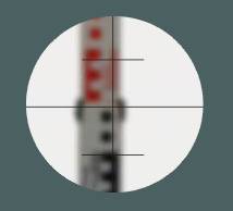
In this view the staff reading is 2.993
Upper stadia = 3.040
Lower stadia = 2.946
Stadia difference = 0.094
Distance to staff = 0.094 x 100 = 9.4 metres
Note that stadia distances have a low level of accuracy, one mm error in staff reading gives a distance error of 0.1 metre
Through the telescope
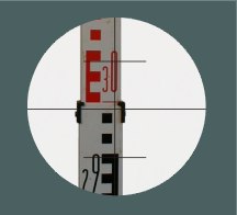
Check that the staff is vertical.
- It is essential that readings are taken when the staff is vertical. If the staff is not vertical the reading will be larger than it should be, as you are measuring a slope distance, and will give errors.
- Some staffs are fitted with a spherical spirit level and handles to help the staff person keep it vertical. Even with a spirit level it is difficult to hold a staff vertical. This difficulty increases in wind.
- To read the staff when vertical the surveyor use the vertical reticule line to direct the staff person to move the top of the staff left or right of the sight line.
- The staff person then slowly tilts the top of the staff towards and away from the instrument so that it will pass through the vertical. The staff will appear to move up and down in the telescope field. The lowest reading is recorded as this is the point at which the staff is vertical.
 <- Staff leaning forward reading high
 <- Staff vertical lowest reading
 <- Staff leaning back reading high
Height References
The aim of this tutorial is to introduce Bench Marks as a height reference.
OS Bench Mark (OSBM).
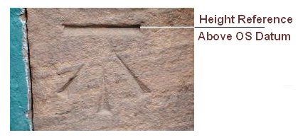
OS Bench Marks are established by the Ordnance Survey to provide height references. They are usually carved into stonework or other stable material that is unlikely to be disturbed.
The centre of the horizontal groove is the height reference.
Heights are given in metres above OS Datum on large scale OS plans and other references.
Temporary Bench Marks (TBM)
Temporary Bench Marks are often established around the survey site. TBMs may be surveyed in to the OS Datum by levelling between the site TBMs and an OSBM.
A site datum may be established instead and all levels referred to a TBM that has been given an arbitrary value (usually 100.000 metres, or a value that ensures all heights will be positive).
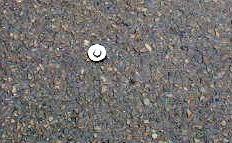
TBMs require to be stable. The main site reference is often a steel pin set in a block of concrete but wooden pegs set in concrete with a nail head providing the reference level are often used.
It is good practice to establish a number of TBMs around the perimeter of a building site as a precaution against the only site height reference being disturbed or dug up part way through the contract.
