Category: R.C.C.

Stairs

Introduction

Reinforced concrete stairs are self-supporting or carried on beams or walls. They are often built around open or lift wells supported according to the type of structure. Staircase with cantilevering treads from a column or wall support are also commonly used for fire escape stairs, etc.

Note – Minimum steel, bar spacing and cover should conform to the requirements specified for slabs and of beams as appropriate.

Flight Supported on Side Beams

The reinforcement detail for a staircase supported by edge beams along each edge is similar to the one supported along its edges by a brick wall. Figure 10.1 shows cross-sectional details of a flight with two types of arrangements. 

12

10.2 Flight Supported on central beam – Figure 10.2 shows the cross-sectional details of a typical staircase supported on a central (stringer) beam. Each step of the the staircase is acting as a cantilever on both sides of the main beam. 

3

Flights and Landings Supported at Ends

Figures 10.3 and 10.4 illustrate two types of stairs with flight and landing supported at ends. Figure 10.3 gives reinforcement details of a flight spanning from outer edge to outer edge ot landing. Figure 10.4 gives reinforcement details of a flight together with its landings spanning from inner edge to inner edge of landings.

45


6

Flight Supported on Brick Wall

Figure 10.5 shows the elevation detail for a straight stair flight with its landings at its ends supported by brick walls.

7

Cranked Beams

Straight stair flights and landings supported by side or centre beams as shown in Fig. 10.1 to 10.3 will require cranked beams. The elevation details of cranked beam is shown in Fig. 10.6.

The method of reinforcing a cranked beam is shown in Fig. 10.6. The bars at the intersections shall be carried for development length past the intersection, and one set of bars shall be cranked inside the other because of fouling. To complete the intersection extra bars, normal to the angle of intersection, are usually added as shown by the bars c and f.

100.JPG

Cantilever Stairs

A typical details of a tread cantilevering from a wall is given in Fig. 10.7. A typical detail of a staircase cantilevering from the side of a wall is shown in Fig. 10.8.

101.JPG


9


Slabless Tread Riser Stairs

A typical detail of a slabless tread riser staircase is given in Fig. 10.9. 

1011

Staircases are normally detailed diagrammatically in plan or section. This is best done by arranging the placing detail and bending schedule adjacent to one another on a single drawing sheet (see Fig. 10.10).

Re-entrant Corners

When tension bars meeting at a corner produce a resultant force resisted by the concrete cover, the bars shall be crossed over and anchored on either side of the cross-over by adequate anchorage length for taking up the stresses in the bar (see Fig. 10.11).

13

Hand Rail Supports

The designer should ensure that adequate consideration is given to the reinforcement detailing for handrail supports. If pockets are left in the concrete into which the hand rail posts are later concreted, the reinforcement shall pass around the pockets and be anchored into the main body of the concrete. If inserts are set into the concrete these should have steel bars passing around them to have sufficient anchorage ties build-in.

Where construction requires bars larger than 10 mm or 16 mm diameter should not be detailed to be rebend, but mild steel bars are recommended if re-bending is unavailable. 

12

Floor Slabs

Solid Slabs

Minimum Reinforcement

In solid reinforced concrete slabs, the reinforcement in either direction expressed as a percentage of the gross-sectional area of the concrete shall not be less than:

a) 0.15 percent where plain bars are used, and

b) 0.12 percent where high yield strength (hot rolled and cold twisted) deformed bars or welded wire fabric are used.

Spacing, Cover and Diameter

Spacing

a) The pitch of the bars for main tensile reinforcement in solid slab shall be not more than thrice the effective depth of such slab or 450 mm, whichever is smaller.

b) The pitch of the distribution bars or the pitch of the bars provided against shrinkage and temperature shall not be more than 5 times the effective depth of such slab or 450 mm, whichever is smaller. Table C-6 (see Appendix C) give area of bars for different spacing and diameter of bars.

Cover

a) The cover at each end of reinforcing bar shall be neither less than 25 mm nor less than twice the diameter of such bar.

b) The minimum cover to reinforcement (tension, compression, shear) shall be not less than 15 mm, nor less than the diameter of bar.

Bar Diameters

The main bars in the slab shall not be less than 8 mm (high yield strength bars) or 10 mm (plain bars) and distribution steel shall not be less than 6 mm diameter bars. The diameter of the bar shall not also be more than one-eighth of the slab thickness.

Simply Supported Slabs

Slabs Spanning in One Direction

A slab that is supported on two opposite sides only by either walls or beams is said to be spanning in one direction. The slab is considered as spanning in one direction even when the slab is supported on all four sides if the effective length of the slab exceeds two times its effective width. The shorter span is to be considered for design.

Figure 9.1 shows the general details of slab spanning in one direction. It clearly indicates the size and thickness of the slab and reinforcement, the cover and the spacing. Slab thickness shall be indicated both in plan and section. Where series of identical bars are used, it is customary to show only one bar. The bars in the shorter direction (main bars) are placed in the bottom layer. At least 50 percent of main reinforcement provided at mid span should extend to the supports. The remaining 50 percent should extend to within 0.1 x l of the support.

The bars in longer direction of the slab are called distribution or transverse steel. These assist in distribution of the stresses caused by the superimposed loading, temperature changes and shrinkage during the hardening process. These bars are placed in the upper layer and tied with the main steel bars to keep them in correct position during concreting.

Slabs Spanning in Two Directions

A simple slab spanning in two directions (ly/lx </= 2) and supported on four brick walls is shown in Fig. 9.2. As the slab is spanning in both directions the reinforcement in each direction shall be considered as main reinforcement. The bars in the shorter direction are generally placed in the bottom layer and tied with the bars iti the longer direction placed above at suitable intervals to keep their relative positions intact during concreting. At least 50 percent of the tension reinforcement provided at mid-span should extend to the supports. The remaining 50 percent should extend to within 0.1 x  lx, or 0.1 x ly, of the support, as appropriate, where lx, and ly, are effective spans in the shorter direction and longer direction, respectively.

Restrained Slabs

When the corners of a slab are prevented from lifting, the following simplified detailing rules may be applied, provided the slab is designed for predominantly uniformly distributed loads.

Note 1 – The analysis of uniformly distributed load and concentrated loads may be done separately, and with appropriate theories. The reinforcement quantities determined in this way should be superimposed.

Note 2 – If an end support is assumed to be a free support in the analysis, but if the character of the structure is such that restraint may nevertheless occur at the support, a restraint moment equal lo half the mid-span moment in the strip concerned may be adopted.

4748


49.JPG

The slabs are considered as divided in each direction into middle strips and edge strips as shown in Fig. 9.3, the middle strip being three-quarters of the width and each edge strip one- eighth of the width.

50

The tension reinforcement provided at mid-span in the middle strip shall extend in the lower part of the slab to within 0.25 x l of a continuous edge, or 0.15 x l of a discontinuous edge.

Over the continuous edges of a middle strip, the tension reinforcement shall extend in the upper part of the slab a distance of 0.15 x l from the support, and at least 50 percent shall extend a distance of 0.30 x l.

At a discontinuous edge, negative moments may arise. They depend on the fixity at the edge of the slab but, in general, tension reinforcement equal to 50 percent of that provided at mid-span extending 0.1 x l into the span will be sufficient.

Torsional Reinforcement

Torsional reinforcement shall be provided at any corner where the slab is simply supported on both edges meeting at that corner and is prevented from lifting unless the consequences of cracking are negligible.

It shall consist of top and bottom reinforcement, each with layer of bars placed parallel to the sides of the slab and extending from the edges a minimum distance of one-fifth of the shorter span. The area of reinforcement per unit width in each of these four layers shall be three-quarters of the area required for the maximum mid-span moment per unit width in the slab (see Fig. 9.4A).

51

Torsional reinforcement equal to half that described in 9.4.6 shall be provided at a corner contained by edges over only one of which the slab is continuous. (see Fig. 9.4B.)

52

Torsional reinforcement need not be provided at any corner contained by edges over both of which the slab is continuous.

A slab shall be treated as spanning one way (in the shorter direction) when ratio of effective span in the longer direction to the effective span in the shorter direction is greater than 2.

Figure 9.5 illustrates curtailment of bars in a restrained slab spanning in two directions based on the above rules using straight bars or bent-up bars.

53

Re-entrant Corners- Diagonal reinforcement shall be placed at all re-entrant corners to keep crack widths within limits (see Fig. 9.6).

54

Cantilever Slabs

The main reinforcement shall be placed in the top of cantilever slab extending to sufficient length over the support and back into the normal span. Tie method of curtailment shall conform to the requirements specified in Section 4.

Support to the top steel of cantilever slabs at spacings -(for stools and chairs) should preferably be specified in the detailing drawing. The bending of the main bars should be such that they contribute to the supporting of the steel, that is, bars that extend to the end should have vertical bends, with a fixing bar at the bend.

The secondary steel at right angles to the support may be designed and detailed to carry construction loading in the propped condition, if necessary.

The deflection in cantilever slabs can be reduced by the addition of compression steel at the bottom. This would also be helpful in counteracting possible reversal of bending moments.

The simplified curtailment rules illustrated in Fig. 9.7 may be used for cantilever slabs when they are designed for predominantly uniformly distributed loads.

5556

Tie Backs and Counter Masses to Cantilevers

Cantilever at the bottom of beams

Ensure, when a cantilever is at the bottom of a beam, the design of the stirrups in the beam provides for moment, shear, hanging tension and, if necessary, torsion.

If possible, provide in the detailing of this steel for placing of the beam steel without the necessity of. the threading of the main beam steel through the cantilever anchorage loops. The details should conform to the basic principles applicable to opening corner in retaining walls and the beams. Figure 9.8 provides three alternative methods of anchoring bars in supporting beams.

57

NOTE- Note the special difficulty induced by bent-up bars in the beam steel:

a) Curtailed bars going to the back of a beam may drift out of position during casting of concrete.

b) Hairpin type bars should be related to the horizontal stirrup spacing, and this may cause difficulties.

c) Loops of 270° are difficult to bend and place in position.

Cantilever at the top of beams

Where the weathering course is 30 mm or less, crank the bars at a slope not exceeding 1 in 6 [see Fig. 9.9(A)]. Ensure that the combination of top bars and stirrups is such as to provide the required restraint. Note that if a bar is laced over and under the beam bars, it is fully restrained provided that the beam top bars are heavy enough and a stirrup is within 50 mm of such bar. If the bar is not so laced, detail the steel to ensure the anchorage against bursting (see Fig. 9.9).

58

 Cantilevers Around Corners

Ensure that, in a corner of a cantilever slab, the detailing is such that tie-back loading and the deflections that arise from this are accounted for. Avoid ‘fan’ type detailing. Take particular care with drainage inlets.

Openings in Slab

Special detailing for openings for lift shafts, large service ducts, etc, in the floors shall be given in the drawing. Such openings shall be strengthened by special beams or additional reinforcement around the openings. Due regard shall be paid to the possibility of diagonal cracks developing at the corners of the openings.

Note – The number, size and position of trimming bars is a function of the design, and should be determined by the designer.

Where openings are small and the slab is not subjected to any special type loading or vibration conditions, the following general detailing rules may be followed around openings (see Fig. 9.10 and 9.11):

a) At least one half the quantity of principal steel intersected by the opening is to be placed parallel to principal steel on each side of the opening extending Ld beyond the edges of the opening.

b) Diagonal stitching bars are put across the corners of rectangular holes or so placed as to frame circular openings. They should be placed both at top and bottom if the thickness slab exceeds 150 mm. The diameter of these bars should be the same as that of, the larger of the slab bars, and their length should be about 80 diameters.

Note – In general openings of diameter less than 250 mm or of size smaller than 200 x 200 mm may be treated as insignificant openings.

5960

Slabs with Welded Wire Fabric

General

Welded wire fabric is either oblong mesh or square mesh arid is supplied in either rolls or flat sheets. The details regarding material, types and designation, dimensions, sizes of sheets or rolls, weight, tolerance, mechanical properties, etc, are all covered in IS : 1566-1982 ‘Specification for hard-drawn steel wire fabric for concrete reinforcement (second revision) ’ (see also Section 1).

Detailing

To ensure that correct size of fabric is laid in right direction, small sketches should be inserted on the plan to indicate the direction of span of the fabric. Details at A and B in Fig. 9.12 indicate square and oblong welded wire fabric, respectively, in plan view of slab.

61

The actual position of the welded wire fabric sheet in slab panels may be shown by a diagonal line together with the description of the mesh used. Bottom sheets should be shown with diagonal drawn from bottom left-hand corner to the top right-hand corner. Top sheets should be shown from top left-hand corner to the bottom right-hand corner. A schedule may also be included in the structural drawing indicating the mesh sizes, length and width, and cutting details for welded wire fabric sheets for different slabs panels. A typical plan is illustrated in Fig. 9.13 (see Section 5 for schedule).

6263

Flat Slabs

General

The term flat slab means a reinforced concrete slab with or without drops, supported generally without beams, by columns with or without flared column heads (see Fig. 9.14). A flat slab may be solid slab or may have recesses formed on the soffit so that the soffit comprises a series of ribs (waffles) in two directions. The recesses may be formed by removable or permanent filler blocks.

64

(see Fig. 9.15)

65

a) Column strip -Column strip means a design strip having a width of 0.25 x l2, but not greater than 0.25 x l1 on each side of the column centre line, where l1 is the span in the direction moments are being determined, measured centre-to-centre of supports and l2 is the span transverse to l1, measured centre- to-centre of supports.

b) Middle strip – Middle strip means a design strip bounded on each of its opposite sides by the column strip.

c) Panel – Panel means that part of a slab bounded on each of its four sides by the Centre line of a column or centre line of adjacent spans.

Proportioning

The minimum thickness of slab shall be 125 mm.

Drops

The drops, when provided, shall be rectangular in plan and have a length in each direction not less than one-third of the panel length in that direction. For exterior panels, the width of drops at right angles to the non- continuous edge and measured from the centre line of the columns shall be equal to one-half the width of drop for interior panels.

Column heads

Where column heads are provided, that portion of a column head which lies within the largest right circular cone or pyramid that has a vertex angle of 90 degree and can be included entirely within the outlines of the column and the column head, shall be considered for design purposes (see 9.13).


Slab Reinforcement

Spacing

The spacing of bars in a flat slab shall not exceed twice the slab thickness, except where a slab is of cellular or ribbed construction.

Area of reinforcement

When drop panels are used, the thickness of drop panel for determination of area of reinforcement shall be the lesser of the following:

a) Thickness of drop, and

b) Thickness of slab plus one-quarter the distance between edge of drop and edge of capital.

Minimum length of reinforcement

a) Reinforcement in flat slabs shall have the minimum lengths specified in Fig. 9.16. Larger lengths of reinforcement shall be provided when required by analysis.

b) Where adjacent spans are unequal, the extension of negative reinforcement beyond each face of the common column shall be based on the longer span.

666768

Anchoring reinforcement

a) All slab reinforcement perpendicular to a discontinuous edge shall have an anchorage (straight, bent or otherwise anchored) past the internal face of the spandrel beam, wall or column of an amount: 

1) For positive reinforcement – not less than 15 cm except that with fabric reinforcement having a fully welded transverse wire directly over the support, it shall be permissible to reduce this length to one-half of the width of the support or 5 cm, whichever is greater; 

2) for negative reinforcement – such that the design stress is developed at the internal face, in accordance with Section 4.

b) Where the slab is not supported by a spandrel beam or wall, or where the slab cantilevers beyond the support, the anchorage shall be obtained within the slab.

When the design is based on the direct design method specified in IS : 456-1978, simplified detailing rules as specified in Fig. 9.17 may be followed. A typical arrangement of bars in a flat slab with drop panels is shown in Fig. 9.17.

6970

Openings in Flat Slabs

Openings of any size may be provided in the flat slab if it is shown by analysis that the requirements of strength and serviceability are met. However, for openings conforming to the following, no special analysis is required (see also 9.6):

a) Openings of any size may be placed within the middle half of the span in each direction, provided the total amount of reinforcement required for the pane1 without the opening is maintained.

b) In the area common to two column strips, not more than one-eighth of the width of strip in either span shall be interrupted by the openings. The equivalent of reinforcement interrupted shall be added on all sides of the openings.

c) In the area common to one column strip and one middle strip, not more than one-quarter of the reinforcement in either strip shall be interrupted by the openings. The equivalent of reinforcement interrupted shall be added on all sides of the openings.

Shear Reinforcement at Column Heads and Dropped Panels – The best method of providing shear reinforcement for slabs at column heads is to use beam cages in one direction and bars in the other direction laid under and on top of the steel in the cages (see Fig. 9.18).

717273

Other methods such as the following may also be used depending upon their suitability:
a) Half or open stirrups suspended from the top steel;

b) Use of serpentine bars (see Fig. 9.19A).

c) Spiders made of bent bars (for deep slabs) (see Fig. 9.19B).

d) Structural steel frames made of plate. 

74

A few more methods of detailing shear reinforcement in flat slabs are given in Fig. 9.20 to 9.22.

75


76


7778

Waffle Slabs

Definition

A waffle flat slab is a two-way joist system. The two-way joist portion may be combined with a solid column head or with solid wide beam sections on the column centre lines for uniform depth construction.

Size of Waffles

Reusable forms of standard size shall be used for economy. These shall provide the width of rib at least 10 cm and spaced not more than 100 cm clear, and depth not more than 3.5 times the minimum width. Standard size may be adopted for these moulds as 50 x 50 cm, 60 x 60 cm, 80 x 80 cm, and 100 x 100 cm and depth as 15, 20, 25, 30, 35, 40, 45, and 50 cm

Detailing of Reinforcement in the Waffle Slab (With Solid Head and Square Interior Panel)

Ensure that at least 50 percent of the total main tension steel in the ribs is carried through at the bottom on to the support and anchored (see Fig. 9.23).

7980


Beams

Arrangement of Bars

The main consideration when arranging bars in beam is to obtain the most economical layout to satisfy the design requirements. It shall also satisfy the relevant rules concerning horizontal and vertical spacing of bars and required bottom and side covers. While fixing the overall dimensions of beams, slenderness limits for beams to ensure lateral stability and span-to-depth ratios to control deflection, shall be kept in view.

The following .points shall also be noted in detailing (see Fig. 8.1).

a) The bars shall be symmetrically placed about the vertical centre line of the beams.

b) Where there are only two bars in a row, these shall be placed at the outer edges.

c) Where bars of different diameter are placed in a single bottom row, the larger diameter bars are placed on the outer side. 

d) Where bars in different horizontal rows have different diameter, the larger diameter bars shall be placed in the bottom row. 

Longitudinal Reinforcement 

Minimum Distance Between Individual Bars

The following rule shall apply:

a) the horizontal distance between two parallel bars shall be usually not less than the following:

1) diameter of the bar, if the diameters are equal;

2) diameter of the larger bar, if the diameters are unequal; and

3) 5 mm more than the nominal maximum size of coarse aggregate.

Note- This does not preclude the use of larger size aggregates beyond the congested reinforcement in the same mmkr, the size of aggregate may be reduced around congested reinforcement to comply with this provision. 

b) Greater horizontal distance than the minimum specified in (a) should be provided, wherever possible. However, when needle vibrators are employed, the horizontal distance between bars of a group may be reduced to two-thirds of the nominal maximum size of aggregate, provided vibrator can be used without difficulty.

c) Where there are two or more rows of bars, the bars shall be vertically in line and the minimum vertical distance between bars shall be 15 mm or two-thirds the nominal maximum size of aggregate or the maximum size of the bar, whichever is the greatest.

The minimum spacing requirements of reinfor-reinforcing bars in beams is illustrated in Fig. 8.1 and Fig. 8.2. 

12


3

Tension Reinforcement

Minimum reinforcement – The minimum area of tension reinforcement shall not be less than that given by the following: 

12

Maximum reinforcement

The maximum area of tension reinforcement shall not exceed 0.04 bD, where b is the width of the beam rib or web and D is the total depth of the beam.

Maximum distance between bars in tension – Unless the calculation of crack widths shows that a greater spacing of bars in acceptable, the following requirements should be fulfilled for control of flexural cracking:

The horizontal distance between parallel reinforcement bars, or groups near tension face of a beam shall not be greater than the value given in Table 8.1 depending on the amount of redistribution carried out in analysis and the characteristic strength of the reinforcement (See Fig. 8.3)

3


4

Compression Reinforcement

The maximum area of compression reinforcement shall not exceed 0.04 bD. Compression reinforcement shall be enclosed by stirrups for effective restraint. The anchorage length of straight bars in compression shall be equal to the development length of bars in compression.

Side Face Reinforcement

Where the depth of the web in a beam exceeds 750 mm side face reinforcement shall be provided along the two faces. The total area of such reinforcement shall be not less than 0.1 percent of the web area and shall be distributed equally on two faces at a spacing not exceeding 300 mm or web thickness, whichever is less (see Fig. 8.4). 5.JPG

Detailing of Shear Reinforcement 

a) A stirrup in the reinforced concrete beam shall pass around or be otherwise adequately secured to the outermost tension and compression reinforcement, and such stirrups should have both its ends anchored properly in any one of the fashion detailed in Fig. 8.5. In T-beams and l-beams, such reinforcement shall pass around longitudinal bars located close to the outer face of the flange. While adopting stirrups, different shapes (see Fig. 8.6) may be considered depending on constructional requirements keeping in view the end anchorage requirements. However, while choosing a particular shape for a particular situation, its validity should be considered from structural point of view. 

67

b) Bent-up Bars

Tensile reinforcement which is inclined and carried through the depth of beam can also be considered to act as shear reinforcement provided it is anchored in accordance with 4.3.5 (see Fig. 8.7). Usually two bars are bent up at a time at an angle 45 degree to 60 degree to the longitudinal axis of the beam but other angles can also be adopted.
It is usual practice to combine bent up bars and vertical stirrups to resist the shear since some of the longitudinal bars are bent up when they are no longer required at the bottom (see Fig. 8.7). 

c) Maximum Spacing

The maximum spacing of shear reinforcement measured along the axis of the member shall not exceed 0.75 d for vertical stirrups and d for inclined stirrups at 45 degree, where d is the effective depth of the section under consideration. In no case shall it exceed 450 mm. 

d) Use of Multi-legged Stirrups

Multi-legged stirrups are required from the consideration of shear stresses in the beam, or where restraint against the buckling of bars in compression is needed. The rules for stirrups reinforcing steel in compression are the same as those for columns. The vertical stirrups may he provided as two-legged stirrups, four- legged stirrups or six-legged stirrups at the same section according to actual requirements (see Fig. 8.8). Open type stirrups as shown in Fig. 8.9 may be used for beam-slab construction where the width of rib is more than 450 mm. 

e)  Stirrups in Edge Beams

Where designer shows stirrups in any edge or spandrel beam, these stirrups shall be closed and at least one longitudinal bar shall be located in each corner of the beam section, the size of this bar is to be at least equal to the diameter of the stirrup but not less than 12 mm. These details P sha 1 be clearly indicated by the designer. Typical cross-sectional details are shown in Fig. 8.10 for normal and upturned edge or spandrel beams. For easier placing of the longitudinal bars in the beam, details for two-piece closed stirrups are also shown. For the same reason, 90 degree stirrup hook is preferred.

f) Minimum Reinforcement

The minimum shear reinforcement in the form of stirrups shall not be less than the following (see Fig. 8.11).

8


9


10


11


1213

However, in members of minor structural importance such a,s lintels, or where the maximum shear stress calculated is less than the permissible value, this provision need not be complied with. 

g) Beam of Varying Depth

Detail stirrup sizes individually where beams have varying depth. A range of stirrup sizes has to be detailed (see fig. 8.12 and also 6.10). 

14

15


16


17

h) Force not Applied to Top of Beam

Where a load transfer is through the bottom or side of a beam (for example, where one beam frames into another), ensure that there is sufficient suspension or hang-up reinforcement at the junction in the main beam in the form of stirrups to transfer the force to the top of the beam. If the load is large, bent-up bars may also be used in addition to stirrups (see Fig. 8.13).

18.JPG

Torsion Reinforcement 

When a member is designed for torsion, reinforcement for the same shall be provided as follows (see Fig. 8.14A)

a) The transverse reinforcement for torsion shall be rectangular closed stirrups placed perpendicular to the axis of the member. The spacing of the stirrups shall not exceed the least of x1, (x1 + y1)/4 and 300 mm, where x1, and y1 are respectively the short and long dimensions of the stirrup. In a beam with multi-legged stirrup, only the stirrup going around the outer face shall be considered to resist torsional force. In members having a complex cross-section (such as I and T-sections), each part (flanges, ribs, webs, etc.) should contain closed stirrups of its own (see Fig. 8.14B and C). 

b) Longitudinal reinforcement shall be placed as close as is practicable to the corners of the cross-section and in all cases there shall be at least one longitudinal bar in each corner of the ties.

c) When the cross-sectional dimensions of the members exceeds 450 mm, additional longitudinal reinforcements shall be provided at the side faces and the total area of such reinforcement shall be not less than 0.1 percent of the web area and shall be distributed equally on two faces at a spacing not exceeding 300 mm or web thickness whichever is lower. 

Curtailment of Reinforcement 

The extent of curtailment of main reinforcement in beams should be related to the.bending moment diagram subject to the conditions specified in Section 4. However, simplified curtailment rules illustrated in Fig. 8.15, 8.16 and 8.17 may be used for continuous beams, simply supported beams and cantilever beams, respectively under the following circumstances:

a) the beams are designed for predominantly uniformly distributed loads; and

b) in the case of continuous beams, the spans are approximately equal (which do not differ by more than I5 percent of the longest).
19

2021


22


23


24

Edge and Spandrel Beam 

T-beams or L- beams are usually designed as internal and external beams supporting a floor slab; where part of the slab form the horizontal portions of the T- or I.-beam.
Where the reinforcement of a slab which is considered as the flange of T- or L.-beam, is parallel to the beam, transverse reinforcement extending to the lengths indicated in Fig. 8.18 shall be provided. If the quantity of such transverse reinforcement is not specially determined by calculations it shall not be less than 60 percent of main reinforcement in the centre of the span of slab constituting the flange.

Corners and Cranked Beams 

Recommendations for various methods of reinforcing corners are giving herein based on reference 6. It is to be noted that closing corners present no major problem, but opening corners require careful detailing (see Fig. 8.l9 and Fig. 8.20).

25


26


27


90 degree Opening Corners With 1 Percent Reinforcement or Less

Where the amount of reinforcement in the beam is equal to or less than 1 percent, detail the reinforcement as shown in Fig. 8.21 or Fig. 8.22, the splay steel being equal to 50 percent of the main steel.

90 degree Opening Corners With More Than 1 Percent Reinforcement

If the area of reinforcement exceeds one percent. provide transverse steel as well as splay steel as in Fig. 8.23. (The use of a splay is also strongly recommended.) 
28


29


30

Cranked Beams

The recommended methods of detailing are shown in Fig. 8.24, 8.25 and 8.26. 

31

32.JPG

Beam and Column Junction

Where a column extends above a beam, bend the beam top reinforcement down into the column but if it is necessary to bend the bars up, detail additional steel as in Fig. 8.27. 

33


Closing Corners

At closing corners provide adequate radii (equal to at least 7.5 bar diameters) and some additional reinforcement as in Fig. 8.28.

34.JPG

Beam of Different Depths

Typical arrangements of reinforcement over the support when the beam on either side of the support are of different depths is shown in Fig. 8.29

35

Tie Members

As a tie is under pure tension there is no tendency to burst like an axially loaded column and therefore binders are not required. But, in order to form the longitudinal bars into a cage, a minimum number of links is used. As there is theoretically no shear or bending moment acting on a tie, only main longitudinal reinforcement is required.

End Details

These shall provide adequate anchors and correct bond lengths. In consideration is the end conditions where a method should be devised to anchor the tie and/or spread its axial load into the connecting members. practice a small splay at the ends of the tie is made to allow for any slight moment that may be induced at the ends. Simple end details for light loading are shown in Fig. 8.30. The ties are shown by the arrows. 

3637


For heavier axial loading, the ends shall be more splayed out to distribute * the load adequately. Typical details are shown in Fig. 8.3 I. In Fig. 8.31 (A and B) it will be seen that as the splay is increased in size, the embedded and hence bond length of the main tie bars is also increased. 

In Fig. 8.31 C extra links or hoops shall be provided as shown to resist the tendency of the large loop to burst under axial load. In Fig. 8.31 the main bars have been shown with double lines for clarity. When detailing they would be shown thick lines in t.he norma! way. 

3839

Haunched Beam

In very heavily loaded beams, for example a warehouse structure, the shear stress and negative bending moment at the supports will be high. An economical method of overcoming this problems is to provide the beams with haunches as shown in Fig. 8.32. There are-no rules governing the size of haunches, but those shown in Fig. 8.32 are considered ideal.

Main Reinforcement in haunches

Figure 8.33 shows the typical main tensile reinforcement in an end external haunch. The main bars are carried through the haunch as if it did not exist, with pairs of bars a, b, c, etc, stopped off in accordance with a cut-off bending moment diagram. Bars h are placed parallel to the haunch to carry vertical links (omitted in the figure for clarity). A similar method of reinforcing to that shown in Fig. 8.33 can also be used for internal haunches. This is shown in Fig. 8.34. 

40


41


42

Stirrups in Haunches

The stirrups in haunches can either be positioned normally to the haunch as shown in Fig. 8.35A, or placed vertically as in Fig. 8.358. Most designers prefer method shown in Fig. 8.35B.

43

If in Fig. 8.33 and 8.34, the h bars were placed near the outside edge of the beam they would foul the outside main horizontal bars. They should, therefore, be placed on the inside as shown in Fig. 8.36 so that two different sets of stirrups are required throughout the whole length of the haunch (see 8.10). 

44.JPG

Beam of Varying Depth

Stirrups need to be detailed individually wherever beams have varying depths and a range of stirrup sizes have to be adopted.  

The different stirrup sizes may be reduced in number by using concertina stirrups (see Fig. 8.12) with the legs lapped with tension lap length. The difference between the lengths of successive groups should be at least 50 mm. In order to maintain the correct size of the member, use closed stirrups at centre-to-centre distances of at least 1000 mm. Ensure that concertina stirrups are properly tied and maintained in position during concreting.

Intersection of Beams 

General

Ensure that, at beam-beam intersections, reinforcement is so arranged that layers in mutually perpendicular beams are at different levels.

Top Steel

It is good practice, for the following reasons, to pass the secondary beam steel over the main beam steel:

a) secondary beam steel is usually of smaller diameter and requires less cover, and

b) secondary beam top reinforcement is available to act as a support for the slab top reinforcement. Where the main beam is very heavily stressed, however, it may be more economical to pass the main beam steel over the secondary reinforcement.

Bottom Steel

To accommodate bottom bars, it is good practice to make secondary beams shallower than main beams, even if by only 50 mm (see Fig. 8.37). Where beam soffits are at the same level, the secondary beam steel should pass over the main beam steel. Unless the secondary beam span is short, bars of diameter less than 25 mm be draped (see Fig. 8.38). Cranking of bottom bars is usually not necessary. If it is required that the beam cages be pre- assembled. provide splice bars 7.6).

Openings in the Web

Adjacent openings for services in the web of flexural members shall be arranged so that no potential failure planes, passing through several openings, can develop. In considering this, the possible reversal of shear force, associated with the development of the flexural overstrength of the members, should be taken into account. 45.JPG

Small square or circular openings may be placed in the mid-depth of the web provided that cover requirements to longitudinal and transverse reinforcement are satisfied, and the clear distance between such openings, measured along the member, is not less than 150 mm. The area of small openings shall not exceed  1000 sq.mm for members with an effective depth,d, less than or equal to 500 mm, or 0.004 d x d when the effective depth is more than 500 mm.

Note – Small openings with areas not exceeding those specified in 8.13.1.are considered not to interfere with the development of the strength of the member. However, such openings must not encroach into the flexural compression zone of the member. Therefore, the edge of a small opening would be no closer than 0.33 d, to the compression face of the member, as required by 8.12.3. When two or more small openings are placed transversely in the web, the distance between the outermost edges of the small openings should be considered as being equivalent to the height of one large opening and the member should be designed accordingly. 8.133 Webs with openings larger than that permitted by 18.12.1 shall be subject to rational design to ensure that the forces and moments are adequately transferred in the vicinity of the openings. This will require the design of orthogonal or diagonal reinforcement around such openings. 8.13.3, Whenever the largest dimension of an opening exceed one-quarter of the effective depth of the member, it is to be considered large. Such openings shall not be placed in the web where they could affect the flexural or shear capacity of the member, nor where the total shear stress exceed 0.36 sqrt. fck, or in potential plastic hinge zones. In no case shall the height of the opening exceed 0.4 d nor shall its edge be closer than 0.33 d to the compression face of the member to ensure that the moments and shear forces can be effectively transmitted by the compression zone of the member.

For openings defined by 8.13.3, longitudinal and transverse reinforcement shall be placed in the compression side of the web to resist one and one-half times the shear across the opening. Shear transfer in the tension side of the web shall be neglected.

Note – Only the part of the web above or below an opening which is in compression should be considered to transmit shear. The stiffness of the tension part is considered to be negligible because of extensive cracking. The amount, location and anchorage of the longitudinal reinforcement in the compression part of the web above the opening must be determined from first principles so as to resist one and one-half times the moment induced by the shear force across the opening. Similarly shear reinforcement in the compression chord adjacent to the opening must resist 150 percent of the design shear force. This is to ensure that no failure occurs as a result of the local weakening of the member due to the opening. Effective diagonal reinforcement above or below the opening, resisting one and one-half times the shear and moment, is also acceptable.

Transverse web reinforcement, extending over the full depth of the web, shall be placed adjacent to both sides of a large opening over a distance not exceeding one-half of the effective depth of the member to resist twice the entire design shear across the opening.

Note- At either side of an opening where the moments and shear forces are introduced to the full section of a beam, horizontal splitting or diagonal tension cracks are to be expected. To control these cracks, transverse reinforcement resisting at least twice the design shear force, must be provided on both sides of the opening. Such stirrups can be distributed over a length not exceeding 0.5 d at either side immediately adjacent to the opening.

A typical detail of reinforcement around a large opening in the web of a beam, complying with the above requirements, are Shown in Fig. 8.39.

46.JPG


Columns

General

Reinforced concrete columns are used to transfer the load of the structure to its foundations. These are reinforced by means of main longitudinal bars to resist compression and/or bending; and transverse steel (ties) to resist bursting force.

The column or strut is a vertical compression member, the effective length of which exceeds three times its least lateral dimension.

Longitudinal Reinforcement

  • In a reinforced column, the area of longitudinal reinforcement shall not be less than 0.8 percent nor more than 6 percent of the gross cross-sectional area of the column. The area of longitudinal reinforcement should normally not exceed 4 percent of the gross cross- sectional area of the column. This percentage can. be considered as the maximum from practical considerations. However where bars from one column have to be lapped with those of another column above, the total maximum percentage of 6 percent may be allowed at the lapping. Proper placing and compacting of concrete should be ensured at the place of lapping.
  • A minimum number of 4 bars shall .be provided in a column and six bars in a circular column with helical reinforcement.
  • The bars shall be not less than 12 mm in diameter and spacing of the bars along the periphery of the column shall not exceed 300 mm.
  • In the case of pedestals in which the longitudinal reinforcement is not taken -into account in strength calculations, nominal longitudinal reinforcement of not less than 0.15 percent of the gross cross-sectional area shall be provided.

Note – Pedestal is a compression member, the effective length of which does not exceed 3 times the least lateral dimension.

  • Dowels and Bar supports

Dowels and bar supports, spacer bars, bar chairs, etc, should be specifically listed on the structural drawing and should be scheduled in that portion of the structure in which they are first required so that they can,be delivered with reinforcement and are available for placement in time. Footing dowels shall be scheduled with footings rather than in column. schedules.

Transverse Reinforcement

A reinforcement concrete compression member shall have transverse or helical reinforcement so disposed that every longitudinal bar nearest to the compression face has effective lateral support against buckling. The effective lateral support is given by transverse reinforcement either in the form of circular rings capable of taking up circumferential tension or by polygonal links (lateral ties) with internal angIe not exceeding 135 degrees. 

Arrangement of Transverse Reinforcement – Where the longitudinal bars are ‘pot spaced more than 75 mm on either side, transverse reinforcement need only to go round comer and alternate bars for the purpose of providing effective supports (see Fig; 7.1).

25.JPG

If the longitudinal bars spaced at a distance not exceeding 48 times the diameter of the tie are effectively tied in two directions, additional longitudinal bars in between these bars should be tied in one direction by open ties (see Fig 7.2)

26.JPG

Where the longitudinal reinforcing bars in a compression member are placed in more than one row, effective lateral support to the longitudinal bars in the inner rows may be assumed to have been provided if:
a) Transverse reinforcement is provided for the outermost row, and 
b) No bar of the inner row is closer to the nearest compression face than three times the diameter of the largest bar in the inner row (see Fig. 7.3).

1.JPG

Where the longitudinal reinforcing bars in compression member are grouped (not in contact) and each group adequately tied with transverse reinforcement, the transverse reinforcement for the compression member as a whole may be provided on the assumption that each group is a single longitudinal bar for purpose of determining the pitch and diameter of the transverse reinforcement. The diameter of such transverse reinforcement need not, however, exceed 20 mm (see Fig. 7.4).

2.JPG

A few examples of column ties are illustrated in Fig. 7.5. 

789101112

Pitch and Diameter of Lateral Ties 

Pitch-The pitch of the transverse reinforcement shall not be more than the least of the following distances (see Fig. 7.6A):

a) the least lateral dimension of the compression member,

b) sixteen times the smallest diameter of the longitudinal reinforcing bar to be tied, and

c) forty eight times the diameter of the transverse reinforcement.

Diameter -The diameter of the polygonal links or lateral ties shall not be less than one-fourth of diameter of the largest longitudinal bar, and in no case less than 5 mm. 

56

Helical Reinforcement (Spirally Reinforced) (see Fig. 7.6B)

Pitch – Helical reinforcement shall be of regular formation with the turns of the helix spaced evenly and its ends shall be anchored properly by providing one and a half extra turns of the spiral preferably with a 135 degrees hook. The pitch of the helical turns shall be not more than 75 mm or one-sixth of core diameter of the column, nor less than 25 mm or 3 times the diameter of steel bar forming helix. Tension lap length shall be provided at lap splices. 

3.JPG

Diameter -The diameter shall be not less than one-fourth of the diameter of the largest longitudinal bar, and in no case less than 5 mm.

Temporary Stirrups- At least two temporary fixing stirrups should be provided to splices in position (see Fig. 7.7) or to stiffen the helically bound columns during fabrication. It is better to detail and schedule such stirrups in the drawing. The stirrups coming above the floor shall not be removed until the next column is erected. 

4.JPG

Large Columns

Where reinforcement for very wide columns is to be fabricated in separate cages and erected in sections, they should be held together by at least 12 mm diameter bars spaced at double the stirrup spacing (see Fig. 7.8). Special requirements, if any, should be indicated by the designer.

Splicing of Column Reinforcement 

  • General

Splicing is normally effected by the lapping of bars. The lengths of laps in the main bars shall conform to the values given in Section 4 (Tables 4.2 to 4.4). The bottom of the bars are normally at floor level. In exceptional cases, the bars may extend over more than one storey, provided that check is made to ensure that intersecting steel from beams, etc, can be placed through the column without difficulty, that the column reinforcement can be properly supported, and the concrete can be properly placed. Some of the bars terminating below floor level require separate splicing (see also Section 4). Typical splice details are shown in Fig. 7.9 (A to E) for both internal and external columns.

  • Where a column at a particular floor is smaller (in cross-section) than the column immediately below it, the vertical bars from the lower column shall be offset to come within the upper column or dowel shall be used. The slope of the inclined portion shall not exceed 1 in 6. In detailing offset column bars, a bar diameter should be added to the desired offset; and in the corner of the square columns, the bars should be offset along the diagonal. 
  • Longitudinal reinforcement bars in square or rectangular columns should be offset bent into the column above. Longitudinal bars in round columns where the column size is not changed should be offset bent if maximum number of bars are desired in the column above. The general practice is to sketch the offset for the corner bars which should be bent diagonally and make this the typical offset dimension for all the bars in the column. 
  • For offset between column faces up to a maximum of 75 mm, the longitudinal bars should be offset bent. When the offset exceeds 75 mm, the longitudinal bars in the column below should be terminated at the floor slab and separate dowels used (see Fig 7.9 B and 7.9 D)
  • Where adjoining beam is not provided, the height of the column equal to say 75 mm above the floor level should be cast along with the lower column so that a kicker can be formed to place the column shutters (see Fig. 7.9 C).

1314


15


16

  • When the bar arrangement changes between floors, bars may extend through, stop off, or require separate dowels (Fig. 7.9B). Each situation requires its own solution. Steel equal to an area and bond capacity to that in the column above shall be extended. Column bars shall be spliced at the top of upstand beams, if available, rather than at floor level. 
  • Where the column verticals are offset bent, additional ties/spirals shall be provided (see Fig. 7.10) and placed at a distance not more than 8 bar diameters from the point of the bend. For practical purpose, 3 closely spaced ties are usually used, one of which may be part of the regularly spaced ties plus two extra ties. The designer shall indicate on the drawing the general arrangement of vertical bars and all tie arrangements.
  • The number of additional ties/spirals should be designed on the assumption that the horizontal thrust to be resisted shall be 1.5 times the horizontal components of the normal stress in the inclined portion of the bars. 
  • Welded splice or other positive connections may be used as butt splices for vertical column bars instead of lapped splices. For bars of size 32 mm and above, such splices or connections may be used to avoid overcrowding of the bars due to extremely long laps which would otherwise be required. Special preparation of the ends of the vertical bars is usually required. Where bars are welded, the most common practice is to provide a square-cut end at the top and a double bevelled end on the bottom of the upper bar to rest on the square cut end (see Fig. 7.11). This permits filling the resulting space with weld metal to develop the splice. Where a welded sleeve or a mechanical device is used, both ends of the bar may be either square cut or standard shear cut, depending upon the type of connection used. Since the point of splice is to be staggered between alternate vertical bars and the splice location will depend upon the design requirements, the designer should indicate the types of splice permissible and their location on the drawing.

Bundled bars

Bundled bars shall be tied, wired or otherwise fastened to ensure that they remain in position. End-bearing compression splices should be held concentric, all bundles of column verticals should be held by additional ties at each end of end-bearing splices, and any short splice bars added for tension should be tied as part of the bundle within the limit of 4 bars in a bundle.: A corner of a tie should be provided at each bundle. 

Column in Flat Slabs

Mushroom heads are normally cast with the columns, and the details of reinforcement should be such that the steel can be formed into a separate cage. Therefore, it should be ensured that the column stirrups end below the mushroom head to enable a properly bonded cage to be positioned (see Fig. 7.12).

Note – The designer shall determine the amount of steel required in the mushroom to control cracks arising from the out-of-balance moments. 

Column-Beam Junction 

Typical details of a . column-beam junction are illustrated in Fig. 7.13. At column-beam intersections, it is better to avoid main beam bars clashing with main column bars. If splice bars are used (see Fig. 7.13), the beam cages may be prefabricated and splice bars placed in position after the beam reinforcement has been positioned in place. This also provides considerable scope for positioning support bars without resorting to cranking and avoiding intersecting beam and column reinforcement. However, this detail requires extra steel due to the additional laps. Where the beam does not frame into the column on all four sides to approximately the full width of the column, ensure that the stirrups are provided in the column for the full depth of the beam, or alternately, that special U-bars are detailed with the beam to restrain the column bars from buckling and to strengthen the concrete in compression. This is especially important where the floor concrete is of a weaker grade than the column concrete (see Fig. 7.14 and 7.15). In general, it is advisable to use U-bars at the non-continuous ends of beams of depth greater than 600 mm.

NOTE – It is important lo note that a joint by itself shall have a dependable strength sufficient to resist the most adverse load combinations sustained by the adjoining members as specified by the appropriate loading code. A higher factor of safety is sometimes necessary for joints. Design and detailing of the joint should be done 1o satisfy this condition. 

17


18


1920

Fig. 7.9 SPLICING OF COLUMN BARS AT INTERMEDIATE FLOORS


21


22

Column with Corbel Joints 

Corbels

A corbel is a short cantilever beam (see Fig. 7.16) in which the principal load is applied in such a way that the distance between the line of action of the load and the face of the supporting member is less than 0.6d and the depth at the outer face of the bearing is greater than one-half of the effective depth at the face of the supporting member.

Main Reinforcement

The main tension reinforcement in a corbel should be not less than 0.4 percent and not more than 1.3 percent of the section at the face of the supporting member, and should be adequately anchored. 

Anchor the reinforcement at the front face of the corbel either by welding it to a transverse bar of equal strength or by bending back the bars to form loops; in either case, the-bearing area of the load should not project beyond the straight portion of the bars forming the main tension reinforcement (see Fig. 7.17 and 7.18). 

NOTE – The limitation on reinforcement percentages is based on the limited number of tests available. 

23


24


2526


27


28


29

Horizontal Force

When the corbel is required to resist a horizontal force in direction H applied to the bearing plate (see Fig. 7.19) because of shrinkage or temperature changes, provide additional reinforcement to transmit this force in its entirety. This reinforcement should be welded to the bearing plate and adequately anchored within the supporting member.

Shear Reinforcement

Provide shear reinforcement in the form of horizontal stirrups distributed in the upper two-thirds of the effective depth of the corbel at the column face. This  reinforcement should have an area of at least one- half of the area of the main tension reinforcement and should be adequately anchored (see Fig. 7.19). 

Detailing of Reinforcement

Columns should be detailed by means of enlarged views. Indicate the levels of the bottom (top of bars at floor level) and top of the column (at top of slab or beam or upstand beam) and the floor height, if necessary. Indicate on the schedule the positions of all intermediate beams. Show each bar mark once, and provide adequate sections showing all main bars and the arrangement of stirrups. Keep in view the effect of providing kickers on levels.

3031


Foundations

Types of Foundations

The following are types of reinforced concrete foundations, the particular type being chosen depending on the magnitude and disposition of the structural loads, and the bearing capacity of the ground. 

a) Individual Column Footing – Generally square in plan but sometimes rectangular or circular.

b) Combined Footing – Combined footing is a common footing to two or more columns in a line. The placing of reinforcement depends on the shape of the bending moment and shear force diagrams considering the soil pressure and the column loads on the footing.

c) Strip Footings – Under columns or walls.

d) Raft Foundation – Covering the whole plan area of structure, detailing being similar to 2-way reinforced solid floor slabs or flat slabs.

e) Pile Foundations – This includes detailing of pile cap and pile portion.

Cover

The minimum thickness of cover to main reinforcement shall not be less than 50 m.m for surfaces in contact with earth face and not less than 40 mm for external exposed face. However, where the concrete is in direct contact with the soil, for example, when a levelling course of lean concrete is not used at the bottom of footing, it is usual to specify a cover of 75 mm. This allows for the uneven surface of the excavation. In case of raft foundation, whether resting directly on soil or on lean concrete, the cover for the reinforcement shall not be less than 75 mm. 

Minimum Reinforcement and Bar Diameter 

The minimum reinforcement according to slab and beam elements as appropriate should be followed, unless otherwise speci P led. The diameter of main reinforcing bars should be not less than 10 mm. 

Detailing Methods 

Foundations should normally be detailed diagrammatically in plan and elevation. 

In case of plan, show diagrammatically the location of foundation reinforcement (similar to slabs) as well as starter bars and stirrups (as for columns). It is preferable for column and wall dowels (starter bars) and the foundation reinforcement to be shown on the same drawing.

In case of elevation, show diagrammatically the location of reinforcement as for beams. In case of pile foundation. detailing of pile is similar to that of columns and detailing of the pile cap supported on piles is similar to that of footing. An indication of the type of soil and its assumed bearing capacity may be specified in the drawing.

Individual Footings 

Individual footings (see Fig. 6.1) are generally square and support a central column. Rectangular footings can be used when the space is restricted in one direction. Individual footings of circular and other shapes can also be used. Figure 6.1 gives typical details of 2 column footing.

Reinforcement Requirements:

Total tensile reinforcement shall be distributed across the corresponding resisting section as given below: 

  1. In one-way reinforced footing, the reinforcement shall be distributed uniformly across the full width of the footing.
  2. In two-way reinforced square footing, the reinforcement extending in each direction shall be distributed uniformly across the full width of the footing.
  3. In two-way reinforced rectangular footing. the reinforcement in the long direction shall be distributed uniformly across the full width of the footing. For reinforcement in the short direction, a central band equal to the width of the footing shall be marked along the length of the footing and portion of the reinforcement determined in accordance with the equation given below shall be uniformly distributed across the central band: 

1.JPG

The remainder of the reinforcement shall be uniformly distributed in the outer portions of the footing. 

Figure 6.2 illustrates placing of transverse reinforcement for rectangular footing. 

23

4

Vertical reinforcement or dowels

Extended vertical reinforcement or dowels of at least 0.5 percent of the cross-sectional area of the supported column or pedestal with a minimum of 4 bars of 12 mm diameter shall be provided. Where dowels are used, their diameter shall not exceed the diameter of column bars by more than 3 mm.

Column bars of diameter larger than 36 mm in compression can be dowelled at the footings with bars of smaller size oi the necessary area. The dowel shall extend into the column a distance equal to the development length of the column bar, and into the footing a distance equal to the development length of the dowel. The development length shall be calculated in accordance with 4.4.2.

For method of detailing see Fig. 6.1.
Note- Where the depth of the footing or footing and pedestal combined is less than the minimum development length in compression required fol dowels (starter bars) of a certain size, the size of dowels (starter bars) may be suitably decreased and the number of dowels increased to satisfy the required area and development length.

To achieve economy, the footings are sloped or stepped towards the edge satisfying the requirements for bending and punching shear. In sloped footing, the slope is generally restricted such that top formwork is not called for in construction. The thickness at the edges shall not be less than 15 cm for footings on soils, nor less than 30 cm above tops of piles in case of footing on piles. 

Combined Footings

  • Combined footings become necessary where the external columns of the structure are close to the boundary of an existing structure and also where the footings of individual columns overlap one another. Such foundations (supporting more than one column/pedestal or a continuous wall) shall be proportioned to resist the design loads and individual reactions, in accordance with appropriate design requirements. The detailing requirements as specified in Section 4 for slabs and beams shall be followed as appropriate. 
  • Detailing
    • For combined footing, detailing of longitudinal and transverse bars is similar to that of beams.
  • Column on edges of footing
    • To prevent shear failure along the inclined plane (corbel type of failure) in footing, where a column is located on the edge, it is advisable to provide horizontal U-type bars around the vertical starter bars. These bars shall be designed for every such column (see Fig. 6.3).

Figure 6.4 (A, B and C) shows typical arrangement of bars in combined footings.

56


78


91011

Continuous Footing Under Walls

In continuous wall foundations, transverse reinforcement should be provided when the projection of the footing beyond the wall exceeds the thickness of the footing (see Fig. 6.5). It is also recommended that longitudinal reinforcement be provided wherever an abrupt change in the magnitude of the load or variation in ground support or local loose pockets may occur along the footing.

12


Raft Foundations

A raft is a foundation unit continuous in two directions, covering an area equal to or greater than the base area of the building. If the raft consists of several parts with varying loads and heights, it is advisable to design the raft with expansion joints between these parts. Joints shall also be provided wherever there is a change in the direction of the raft and should be detailed on the drawing. The detailing requirements as specified in Section 4 for beams and columns may be followed as appropriate. 

Minimum reinforcement in either direction shall not be less than 0.15 percent of the gross sectional area for mild steel reinforcement and 0.12 percent in case of high strength deformed bars.

Detailing

For raft foundation, detail both the longitudinal and transverse bars generally in accordance with the rules for slabs and beams except cover and bar supports. While detailing reinforcement in raft foundation. construction method and sequence of construction are to be specified which should include the following:

  1. Position of construction joints,
  2. Position of movement joints, and
  3. Position of water bar joints.

The location of lap splices in raft should be detailed with care as the direction of bending will differ from suspended members.

Placing of Bar Supports

Where top reinforcement is required, consideration should be given to the method of supporting this with chairs and edge U-bars. This must be carried out in accordance with the specification for the job and should take into account construction sequence. weight of top steel and depth of foundation. The suggested spacing of supports i.e 30 times the diameter of supporting bars using chairs having diameter of at least 12 mm. I the diameter of chairs should be such that the), do not bend or buckle under the weight of reinforcement and other incidental loads during construction.

Ducts and Trenches

Where ducts and trenches occur in rafts, special attention should be given to detailing continuity of top reinforcement. specially where moment transfer is required (see Fig. 6.6).

13

Pile Foundation

  • Driven Precast Concrete Pile

a) The longitudinal reinforcement shall be provided in precast reinforced concrete piles for the entire length. All the main longitudinal bars shall be of the same length with lap welded at joints and should fit tightly into the pile shoe if there is one. Shorter rods to resist local bending moments may be added but the same should be carefully detailed to avoid any sudden discontinuity of the steel which may lead to cracks during heavy driving.

The area of main longitudinal reinforcement shall not be less than the following percentages of the cross-sectional area of the piles:

1) For piles with length less than 30 times the least width- 1.25 percent.

2) For piles with length 30 to 40 times the least width- 1.5 percent.

3) For piles with length greater than 40 times the least width- 2 percent.

b) The lateral reinforcement is of particular importance in resisting the driving stresses induced in the piks and should be in the form of hoops or links and of diameter not less than 6 mm. The volume of lateral reinforcement shall not be less than the following (see Fig. 6.7):

1) At each end of the pile for a distance of about 3 times the least width-not less than 0.6 percent of the gross volume of that part of the pile; and

2) In the body of the pile-not less than 0.2 percent of the gross volume of pile.

The spacing shall be such as to permit free flow of concrete around it. The transition between the close spacing of lateral reinforcement near the ends and the maximum spacing shall be gradually over a length of 3 times the least width of the pile. 

The cover of concrete over all the reinforcement including ties should not be less than 40 mm. But where the piles are exposed to seawater or water having other corrosive content, the cover should be nowhere less than 50 mm.

Piles should be provided with flat or pointed coaxial shoes if they are driven into or through ground, such as rock, coarse gravel, clay with cobbles and other soils liable to damage the concrete at the tip of the pile. The shoe may be of steel or cast iron. Shapes and details of shoca depend on the nature of ground in which the pile is driven. In uniform clay or sand the shoe may be omitted.

Where jetting is necessary for concrete pilu, a jet tube may be cast into the pile, the tube being connected to the pik shoe which is provided with jet holes. Generally, a central jet is inadvisable, as it is liable to become choked. At least two jet holes will be necessary on opposite sides of the shoe, four holes give best results. Alternatively, two or more jet pipes may be attached to the sides of the pile.

Reinforcement requirement

A pile shall be reinforced in the same way as the column, with the main bars on the periphery and secondary bars (binders or links) around main bars. In addition the main bars shall be bent inwards at the lower end and welded to the shoe made of chilled cast iron or steel.

Spacer bars

To ensure the rigidity, pile spacer bars shall be used as shown in Fig. 6.8. The spacer bars or forks can be of cast iron, pressed steel or a length of steel pipe with slotted ends to fit the main reinforcing bars. They can be detailed on the drawing, at 1.5 m centres along the full length of the pile. The fork may be placed diagonally at each position across the section as shown in Fig. 6.8.

1415

  • Cast-in-situ Piles or Bored Piles

Reinforcement requirement

The design of the reinforcing cage vary depending upon the driving and installation conditions, the nature of the subsoil and the nature of load to be transmitted by the shaft. that is. axial or otherwise. The minimum area of longitudinal reinforcement (mild steel or deformed bars) within the pile shaft shall be 0.4 percent of the sectional area calculated on the basis of outside area of casing of the shaft.

The curtailment of reinforcement along the depth of the pile. in general, depends on the type of loading and subsoil strata. In case of piles subject to compressive load only, the designed quantity of reinforcement may be curtailed at appropriate level according to the design requirements. For piles subjected to uplift load, lateral load and moments, separately or with compressive loads. it may be necessary to provide reinforcement for the full depth of pile. In soft clays or loose sands, or where there is likelihood of danger to green concrete due to driving of adjacent piles. the reinforcement should be provided up to the full pile depth with lap welds at joints regardless of whether or not it is required from uplift and lateral load considerations. However, in all cases. the minimum reinforcement should be provided in the full length of the pile.

Piles shall always be reinforced with a minimum amount of reinforcement as dowels, keeping the minimum bond length into the pile shaft and with adequate projection into the pile cap.

Clear cover to all main reinforcement in pile shaft shall be not less than 50 mm. The laterals df a reinforcing cage may be in the form of links or spirals. The diameter and spacing of the same is chosen to impart adequate rigidity to the reinforcing cage during its handling and installations. The minimum diameter of the links or spirals shall be 6 mm and the spacing of the links or spirals shall be not less than 150 mm.

Under-reamed Piles

The minimum area of longitudinal reinforcement in stem should be 0.4 percent. Reinforcement is to be provided in full length. Transverse reinforcement shall not be less than 6 mm diameter at a spacing of not more than the stem diameter or 300 mm whichever is less. In under-reamed compaction piles, a minimum number of four 12-mm diameter bars shall be provided. For piles of lengths exceeding 5 m and of 375 mm diameter, a minimum number of six 12-mm bars shall be provided. For piles exceeding 400 mm diameter, a minimum number of six 12-mm bars shall be provided. The circular stirrups for piles of lengths exceeding 5 m and diameter exceeding 375 mm shall be minimum 8-mm diameter bars.
The minimum clear cover over the longitudinal reinforcement shall be 40 mm. In aggressive environment of sulphates, etc. it may be increased to 75 mm. 

Figure 6.9 gives typical details of a bored cast-in-situ under-reamed pile foundation.

16.JPG

  • Pile Caps

The pile cap usually supports column and this is positioned at the centre of gravity of the pile group, so the pile cap incorporates column dowel bars in exactly the same way as provided in column bases. Allowance shall be made in length and width of the cap to allow for piles being slightly out of true position after being driven.

General consideration

  • The pile cap along with the column pedestal shall be deep enough to allow for the necessary anchorage of the column and pile reinforcement. Although they are assumed to act as a simply supported beam and are designed for the usual conditions of bending moment and shear force, there is a tendency to fail in bursting due to high principal tension. This should be resisted by reinforcement going around outer piles in the group (usually # 12 @ 150).
  • Generally adopted configuration for pile caps along with plan arrangement of reinforcement details are shown in Fig. 6.10.
  • The clear overhang of the pile cap beyond the outermost pile in the group shall normally be 100 to I50 mm, depending upon the pile size.

17.JPG

  • A levelling course of plain concrete of about 80 mm thickness may be provided under the pile caps, as required.
  • The clear cover for the main reinforcement for the bottom of cap shall not be less than 60 mm. 
  • The reinforcement from the pile should be properly tied to the pile cap.
  • A typical arrangement of bars in a pile cap supporting a column between two piles is illustrated in Fig. 6.1 I and typical details of a pile cap resting on 3 piles is illustrated in Fig. 6.12.

Grade Beams

  • The grade beams supporting the walls shall be designed taking due account of arching effect due to masonry above the beam. The beam with masonry behaves as a deep beam due to composite action.
  • The minimum overall depth of grade beams shall be 150 mm. The reinforcement at the bottom should be kept continuous and an equal amount may be provided at top to a distance of quarter span both ways from pile or footing centres as the case may be. The longitudinal reinforcement both at top and bottom should not be less than three bars of 10 mm diameter (mild steel) and stirrups of 6 mm diameter bars spaced at a maximum spacing of 300 mm (see Fig. 6.13).
  • In expansive soils, the grade beams shall be kept a minimum of 80 mm clear off the ground. In other soils.‘beams may rest on ground over a levelling concrete coarse of about 80 mm (see Fig. 6.14).
  • In case of exterior beams over piles in expansive soils, a ledge projection of 75 mm thickness and extending 80 mm into ground (see Fig. 6.14), shall be provided on outer side of beams.

1819


2021

222324


General Detailing Requirements

Cover

Reinforcement shall have concrete cover (nominal) and the thickness of such cover (exclusive of plaster or other decorative finish) shall be as follows:

  1. At each end of reinforcing bar not less than 25 mm, or twice the diameter of such bar whichever is greater;
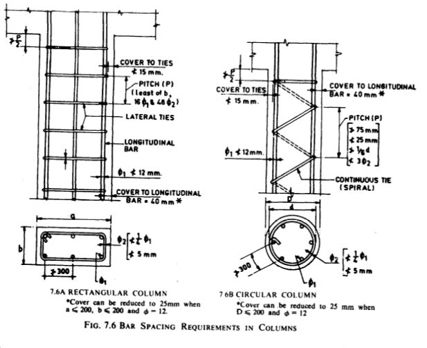
  2. For a longitudinal reinforcing bar in a column not less than 40 mm or the diameter of such bar whichever is greater. In the case of columns with a minimum dimension of 20 mm or tinder, whose reinforcing bars do not exceed 12 mm, the cover may be reduced to 25 mm;
  3. For longitudinal reinforcing bar in a beam not less than 25 mm or the diameter of such bar, whichever is greater;
  4. For tensile, compressive, shear or other reinforcement in a slab not less than I5 mm or the diameter of such reinforcement, whichever is greater; and
  5. For any other reinforcement not less than 15 mm or the diameter of such reinforcement, whichever is greater.

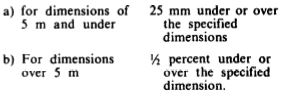
Note – The values of cover suggested are nominal cover as specified in the drawings. The cover shall in no case be reduced by more than one-third of the specified cover or 5 mm whichever is less. During construction it is essential to ensure that these tolerances are met.

  • Increased cover thickness may be provided when the surfaces of concrete members are exposed to the action of harmful chemicals (as in the case of concrete in contact with earth contaminated with such chemicals), acid, vapour, saline atmosphere, sulphurous smoke (as in the case of steam-operated railways), etc, and such increase of cover may be between I5 and 50 mm over the values given in 4.1 above as may be specified by the Engineer-in-Charge. However, in no case cover should exceed 75 mm. 
  • For reinforced concrete members of marine structures totally immersed in seawater, the cover shall be 40 mm more than that specified in 4.1, but total cover should not exceed 75 mm. 
  • For reinforced concrete structures/ structural members, periodically immersed in seawater or subject to sea spray, the cover of concrete shall be 50 mm more than that specified in 4.1, but total cover should not exceed 75 mm. 
  • For concrete of grade M25 and above, the additional thickness of cover specified in 4.1.1 to 4.1.3 may be reduced by half. 

Development of Stress in Reinforcement

  • Development Length of Bars in Tension or Compression – The calculated tension or compression in any bar at any section shall be developed on each side of the section by an appropriate development length or end anchorage or by a combination thereof.

Note – Development length is the embedded length of reinforcement required to develop the design strength of the reinforcement at a critical section. Critical section for development of reinforcement in flexural members are at points of maximum stress and at points within the span where adjacent reinforcement terminates, or is bent. Provisions of 4.6.3 (c) should be satisfied at simple supports and at points of inflection.
123

  • Design bond stress in limit state design method for plain bars in tension shall be as follows: 

4.JPG

For deformed bars, these values shall be increased by 60 percent. For bars in compression, the values of bond stresses for bars in tension shall be increased by 25 percent. 

Anchoring Reinforcing Bars 

It is important to note that when a bar is subjected to both tension and compression, the anchorage value should correspond to the one which gives the maximum value, and at the same time individual requirements (with respect to tension and compression) are also satisfied as specified in 4.3.1 to 4.3.3.

  • Anchoring Bars in Tension 

Deformed bars may be anchored in straight lengths (without end anchorages), provided the development length requirements are satisfied. Plain bars should not be normally anchored through straight lengths alone and should be provided with hooks.
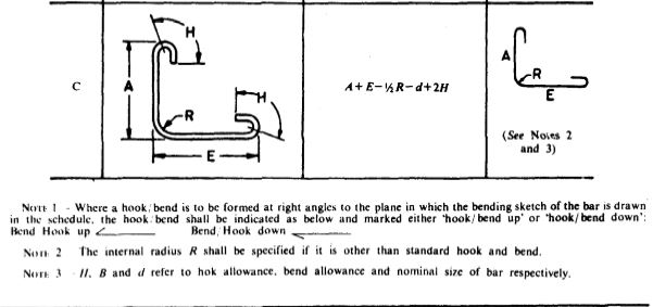
Bends and hooks 

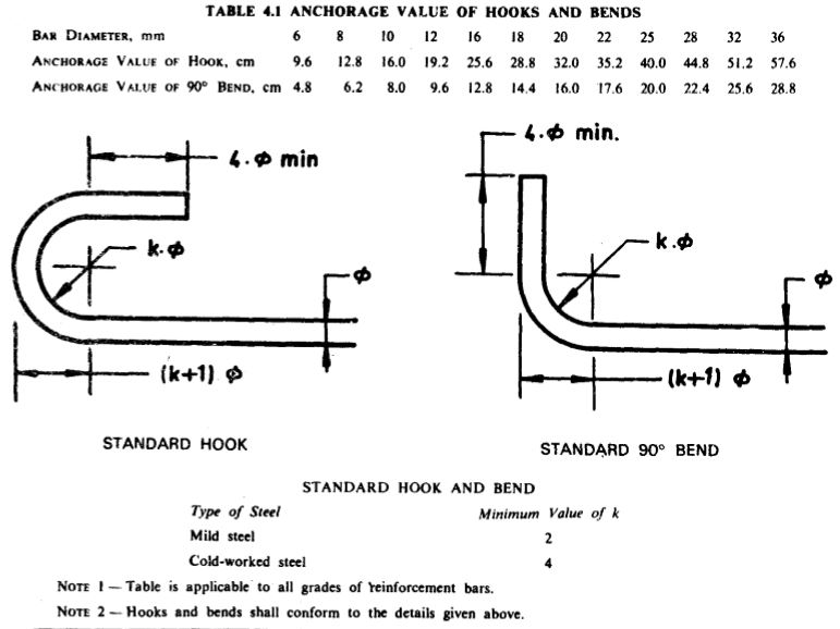
a) Bends – The anchorage value of a standard bend shall be taken as 4 times the diameter of the bar for each 45 degree bend subject to a maximum of 16 times the diameter of the bar.

b) Hooks – The anchorage value of a standard U-type hook shall be equal to 16 times the diameter of the bar. 

The anchorage values of standard hooks and bends for different bar diameters are given in Table 4.1. 

  • Anchoring Bars in Compression

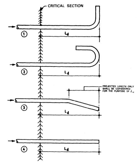
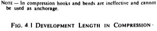
The anchorage length of straight bar m compression shall be equal to the development length of bars in compression as specified in 4.2.2. The projected length of hooks, bends and straight lengths beyond bends, if provided for a bar in compression, should be considered for development length (see Fig. 4.1).

5.JPG

6.JPG

7

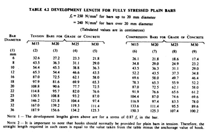
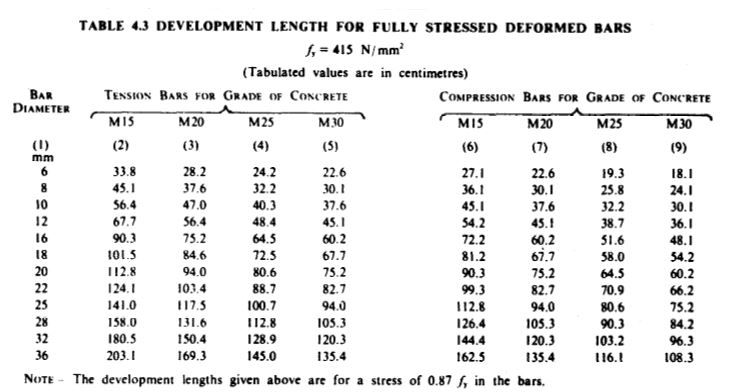
  • The development length values for fully stressed bars in tension as well as compression based on 4.2.2 are given in Tables 4.2, 4.3 and 4.4.

NOTE- If the amount of steel provided at a design section is more than that required from design consideration, the development length given in Tables 4.2, 4.3 and 4.4 may be modified as: 

8.JPG

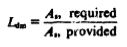
Unless otherwise specified, Ldm modified development length should be used in detailing reinforcement.

  • Mechanical Devices for Anchorage – Any mechanical or other device capable of developing the strength of the bar without damage to concrete may be used as anchorage with the approval of the Engineer-in-Charge. 
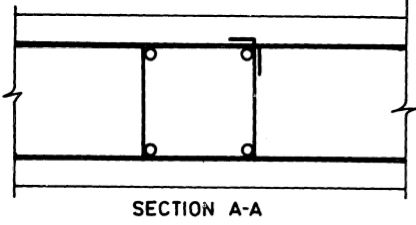
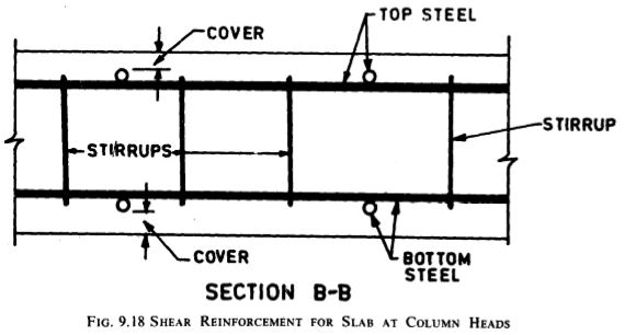
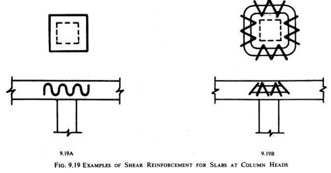
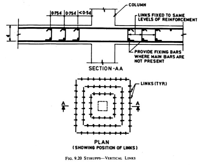
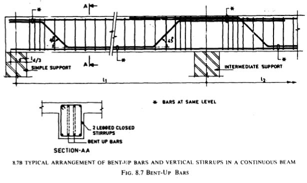
  • Anchoring Shear Reinforcement 

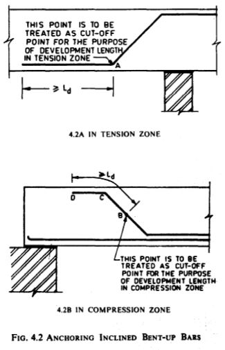
a) Inclined bars – The development length shall be as far bars in tension; this length shall be measured as under:

  1. In tension zone, from the end of the sloping or inclined portion of the bar (See Fig. 4.2A), and
  2. In the compression zone, from the mid depth of the beam (see Fig. 4.2B). 

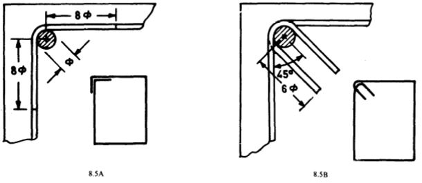
b) Stirrups and ties-Not withstanding, any of the provisions of this Handbook, in case of secondary reinforcement, such as stirrups and transverse ties, complete development length and anchorage shall be deemed to have been provided when the bar is bent through an angle of at least 90 degree round a bar of at least its own diameter and is continued beyond the end of the curve for a length of at least eight diameters, or when the bar is bent through an angle of 135 degree and is continued beyond the end of the curve for a length of at least six bar diameters or when the bar is bent through an angle of 180° and is continued beyond the end of the curve for a length of at least four bar diameters. 

  • Special Members

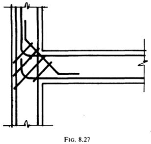
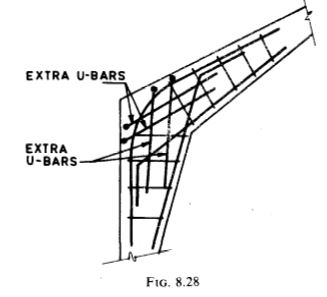
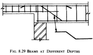
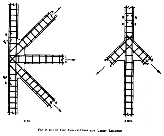
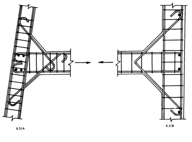
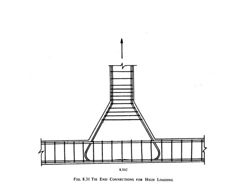
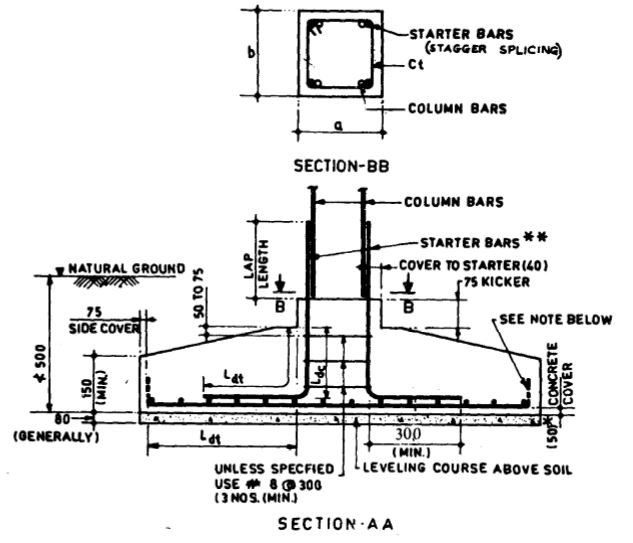
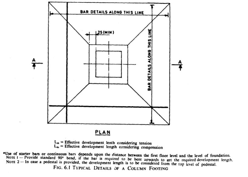
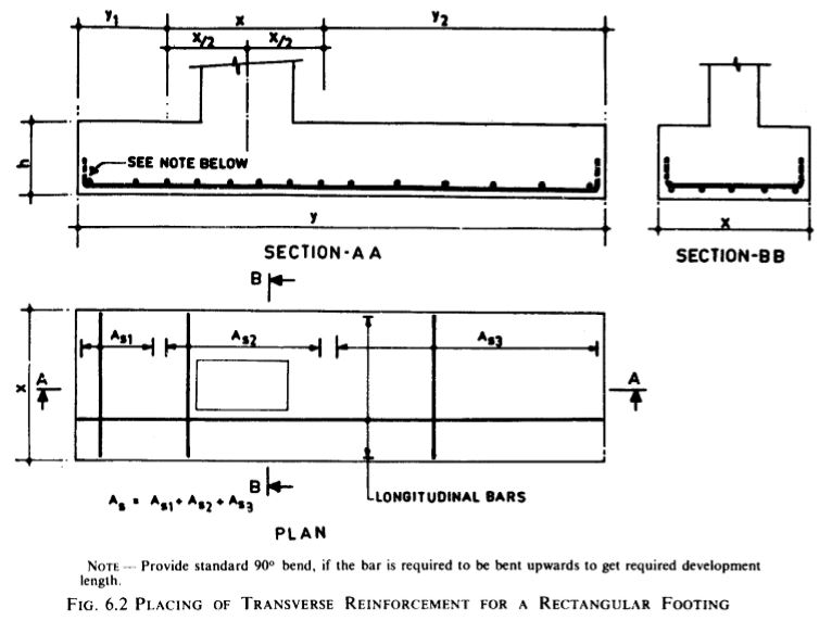
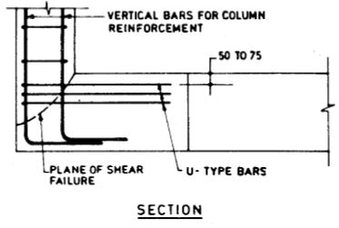
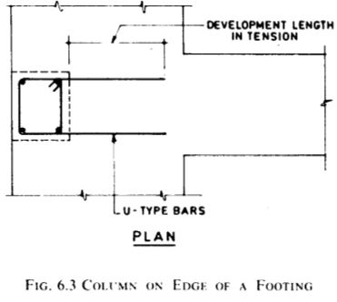
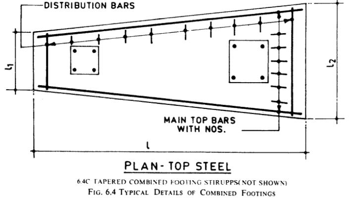
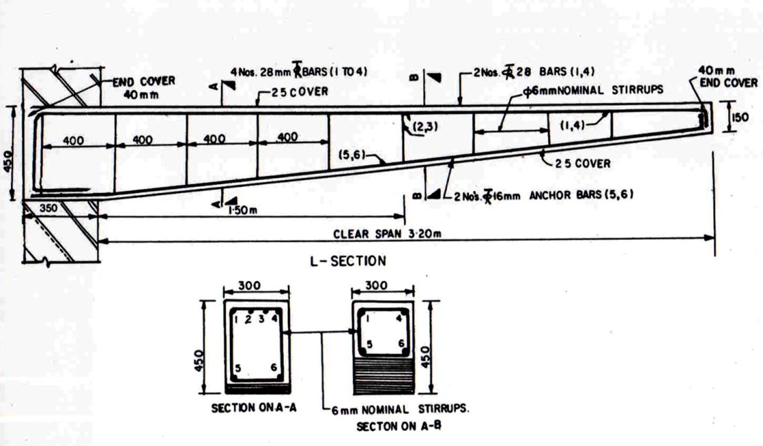
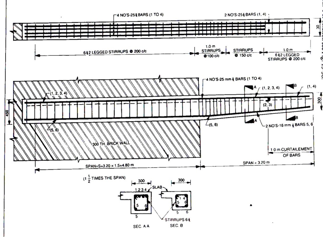
Adequate end anchorage shall be provided for tension reinforcement in flexural members where reinforcement stress is not directly proportional to moment, such as sloped, stepped or tapered footings, brackets, deep beams and members in which the tension reinforcement is not parallel to the compression face. 

9


10


11.JPG


12.JPG

Reinforcement Splicing

  • Splicing is required to transfer force from one bar – t,o another. Methods of splicing include lapping (see 4.4.2), welding and mechanical means (see – 4.4.3)
  • Where splices are provided for continuity in the reinforcing bars (tension bars in beams), they shall be as far as possible away from the sections of maximum stress and be staggered. It is recommended that splice in flexural members should not be at sections where the bending moment is more than 50 percent of the moment of resistance of the section. Not more than half the bars shall & spliced at a section.
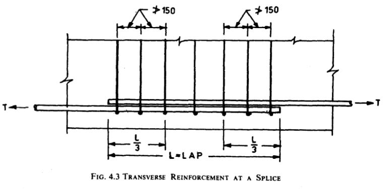
  • Where more than one half of the bars are spliced at a section or where splices are made at points of maximum stress, special precautions shall be taken, such as increasing the length of lap and/or using spirals or closely spaced stirrups around the length of the splice.

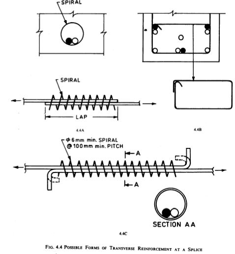
Note 1 – The stirrups provided should be able to resist a tension equal to the full tensile force in the lapped bars and should be provided in the outer one-third of the lap length at both ends with at least three stirrups on either side (see Fig. 4.3). In case of thick bars (say diameter > 28 mm), lap splices should be completely enclosed by transverse reinforcement, for example, in the form of small compact stirrups or spirals [see Fig. 4.4 (A and B)].

Note 2 – Careful detailing is necessary when reinforcements are to be spliced. Therefore location and details of splices should be determined at the design stage itself and indicated in the drawing. Preferably splicing details should not be left to be decided at the site of construction. 

Lap Splices 

  1. Diameter of bars for lap splicing – Lap splices shall not be used for bars larger than 36 mm. For larger diameters, bars may be welded (see Appendix A). In cases where welding is not practicable, lapping of bars larger than 36 mm may be permitted, in which case additional spirals should be provided around the lapped bars (see Fig. 4.4A).
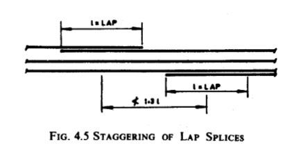
  2. Staggering of lap splices – Lap splices shall bc considered as staggered if the centre-to centre distance of the splices is not less than 1.3 times the lap length (see Fig. 4.5) calculated as given in (c) below. Bars could be lapped vertically one above the other or horizontally, depending upon the space requirement.
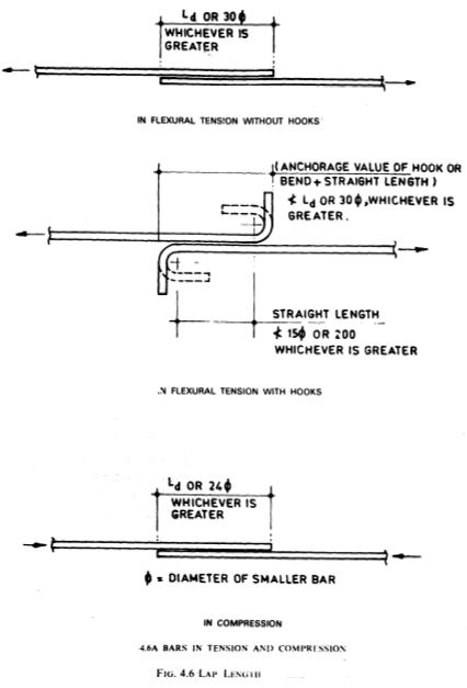
  3. Lap length in tension – Lap length including anchorage value of hooks in flexural tension shall be Ld or (30 x diameter) whichever is greater and for direct tension 2 Ld or (30 x diameter) whichever is greater. The straight length of the lap shall not be less than (15 x diameter) or 200 mm, whichever is greater (see Fig. 4.6).

where Ld= development length

Note- Splices in direct tension members shall be enclosed in spirals made of bars not less than 6 mm in diameter with pitch not more than IO cm. Hooks/bends shall be provided at the end of bars in tension members (see Fig. 4.4C). 

4. Lap length in compression – The lap length in compression shall be equal to the development length in compression calculated as in 4.2.2 (see Tables 4.2, 4.3 and 4.4), but not less than 24 x diameter.

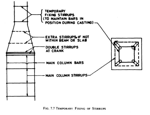
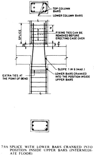
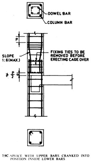
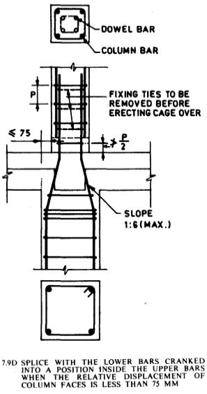
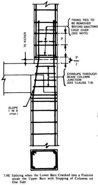
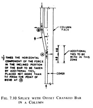
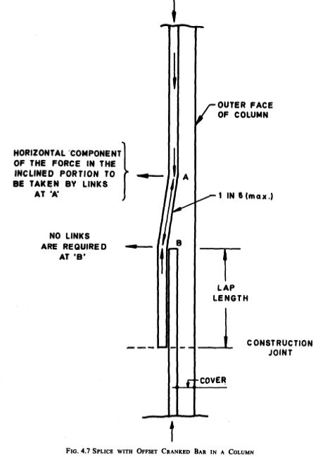
5. Requirement of splice in a column – In columns where longitudinal bars are offset at a splice, the slope of the inclined portion of the bar with the axis of the column shall not exceed 1 in 6, and the portions of the bars above and below the offset shall be parallel to the axis of the column. Adequate horizontal support at the offset bends shall be treated as a matter of design, and shall be provided by metal ties, spirals, or parts of the floor construction. Metal ties or spirals so designed shall be placed near (not more than 8 x diameter) from the point of bend. The horizontal thrust to be resisted shall be assumed as 1.5 times the horizontal component of the nominal force in the inclined portion of the bar (see Fig. 4.7). Offset bars shall be bent before they are placed in the forms. Where column faces are offset 75 mm or more, splices of vertical bars adjacent to the offset face shall be made by separate dowels overlapped at specified about.

Note – It is to be noted that in Fig. 4.7. additional stirrups will be required only near the bottom crank.

6. Bars of different diameters – When bar of two different diameters are to be spliced, the lap length shall be calculated on the basis of diameter of the smaller bar.

1314.JPG15.JPG16

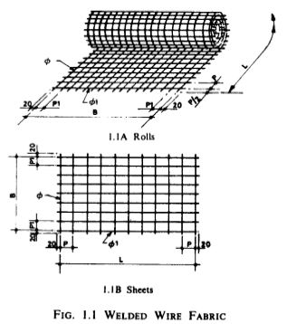
Lap splices in welded wire fabric: 

  1. The fabric is supplied in long mats/rolls and it is rarely necessary to have a joint of the main wires. The rigidly connected cross-members provide mechanical anchorage. Adequate lapping where necessary may be provided with a comparatively short lap when cross wires occur within the lap.
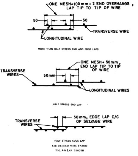
  2. In structural slabs, laps in regions of maximum stress shall be avoided. Such splices, where used for either end or edge laps. shall be made so that the distance between outermost cross wires is not less than the spacing of the wire parallel to the lap plus 100 mm (see Fig. 4.6).
  3. In other cases for end laps, welded wire fabric shall be lapped not less than one mesh plus 50 mm, that is, the length of the lap shall be 50 mm greater than the spacing of wires parallel to the lap. For edge laps, a lap of 50 mm is sufficient (see Fig. 4.6).
  4. These requirements for lapping should be covered by suitable notes in the general specifications. But whether specified by wordings or shown on plans, certain dis- tinction should be made between ‘edge laps’ and ‘end laps’.
  5. The width of an edge lap shall be indicated as the centre-to-centre distance between the outside of longitudinal salvage wires of the overlapping sheets as illustrated in Fig. 4.6.
  6. The length of an end lap shall be indicated as the top-to-top distance between the ends of the longitudinal wires of the overlapping sheets.17

18

Welded Splices and Mechanical Connections:

Where the strength of a welded splice or mechanical connection has been proved by tests to be at least as great as that of the parent bar, the design strength of such connections shall be taken as equal to 80 percent of the design strength of the bar for tension splice and 100 percent of the design strength for the compression splice. However, 100 percent of the design strength may be assumed in tension when the spliced area forms not more than 20 percent of the total area of steel at the section and the splices are staggered at least 600 mm centre-to-centre.

The choice of splicing method depends mainly on the cost, the grade of steel, the type of reinforcement, generally high bonding, the possibility of transferring compressive and/ or tensile stresses and the available space in the section concerned. The designer shall specify the splicing method and the conditions under which it is to be carried out.

Mechanical coupling devices shall be arranged so that as small a number as possible affect a single section.They should, in addition, be placed outside the most highly stressed sections.

Sleeve splicing – If correctly used, sleeve connections may transmit the total compressive or tensile stress. In general, the use of these sleeves is governed by various conditions laid down in the agreement for the method or, in the absence of recommendations, by preliminary testing.

During assembly, particular care shall be taken to ensure that the lengths introduced into the sleeve are sufficient. 

These lengths should be marked before hand on the ends of the bars to be spliced except when a visual check on penetration is possible (for example, sleeve with a central sight hole):

a) Threaded couplers (see Fig. 4.8)

In order to prevent any decrease in the end sections of the bar as a result of threading (with V- form or round threads), they can be:
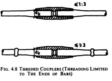
 19

1) upset;

2) for long units, fitted with larger section threaded ends by flash welding; or

3) fitted with a threaded sleeve by crimping.

Another solution consists of threading the ends but only taking into consideration the nominal section of the threaded end, that is, reducing the permissible stress in the reinforcement.

The ends of the sleeve shall be slightly reduced in section, in order to prevent overstressing of the first few threads.

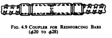
There are, at present, reinforcing bars with oblique, discontinuous., spiral ribs, allowing splicing with a special sleeve with internal threads.

This same process is used to splice prestressing bars, and in order to prevent confusion between reinforcing bars and prestressing steels, the direction of threading is reversed (see Fig. 4.9). 

20

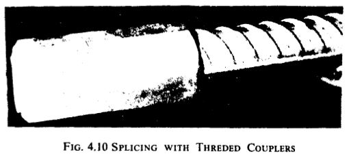
Two lock nuts. tightened on each side of the sleeve into which the reinforcing bars are introduced to the same depth, prevent -any accidental unscrewing due to slack in the threads (splices not under tension). The nuts are tightened with a torque wrench. This device is also used for splicing prefabricated elements. These joints are generally 100 percent efficient under both tension and compression. To decrease the itt-siru operations. one of the ends is generally fitted with its sleeve in advance and the other bar to be joined with the sleeve should remain manoeuvrable until the splice has been made (see Fig. 4. 10)

6.JPG

b) Coupling with a crimped sleeve

Crimped sleeves constitute a method of splicing limited to relatively large diameter deformed reinforcing bars. It consists of the introduction of the bars to be spliced into a sleeve which is crimped by means of a hydraulic crimping tool onto the ribbed bars in order to fill the voids between them and the inner surface of the sleeve. The ribs on the bar penetrate into the relatively softer steel of the sleeve and the ribs work in shear.

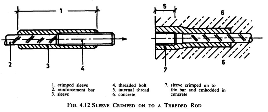
During crimping the sleeve lengthens, and the other reinforcing bar to be spliced should be displaceable at this moment. The size of the crimping device requires a bar interspacing of at least 10 cm (see Fig. 4.11). Splicing by crimping is also possible with reinforcing bars of differing diameter. The same method also enables threaded steel rods to be spliced to reinforcing bars using high strength threaded bolts (see Fig. 4.12).

12

c) Coupling with injected sleeves

These couplings are a special case of sleeve splicing; the stresses are distributed by the shear strength of the product injected between the ends of the bars to be sleeve spliced:

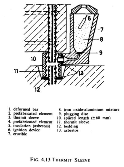
1)With the ‘Thermit’ sleeve the space between the deformed bars and the sleeve, whose internal surface is also ribbed, is tilled with a special molten metal. This molten metal is prepared in a crucible, which is in communication with the sleeve, by igniting a mixture consisting mainly of iron oxide and aluminium powder. The strength of the sleeve may be increased by using a larger sleeve diameter (see Fig. 4.13).

The sleeve is shorter ‘but wider than that used in the crimping method. The bars are not in contact.

The splice may be made in any direction as long as space allows the crucible to be put into place.

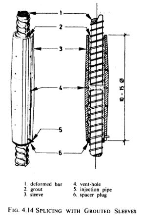
2) Similar method is the injection of grout or an epoxy resin between the sleeve and the bars. The length of the sleeve is necessarily greater (see Fig. 4.14). 

3.13.2.JPG4

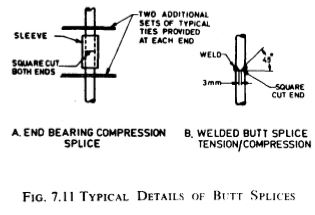
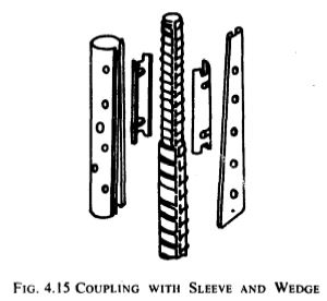
d) Butt splices – For this purpose open flanged sleeves made from steel strip can be used. They are tightened onto the bars by the introduction of a flat tapered wedge (see Fig. 4.15).

The end sections, in contact within the device, shall be perfectly at right angles to the axis of the spliced bars.

Another method involves the use of 4 small diameter ribbed bars which are tightened, using pliers, with 3 ring-clamps. The advantage of this method, in comparison to the previous one, is the fact that it allows a portion of the tensile stress to be taken up.

For bars with ribs in the form of a thread, a butt splice may be made with a sleeve, but with greater facility.

There are also sleeves consisting of a metallic cylinder, the internal diameter of which fits the bars to be spliced. This sleeve is fixed to one of the reinforcing bars by a few welding points: a hole at the centre of the sleeve enables one to check that there is contact between the bars. This economical method of splicing, which is easy to apply, can only transmit compressive stresses. 

5

Main advantages and disadvantages of mechanical coupling:

  1. The use of mechanical couplers is frequently justified when space does-not allow lapping, although crimping and tightening tools require accessibility which may reduce this advantage.
  2. This splicing method often requires more careful cutting of the reinforcing bar, a check which is more difficult than in the case of lapping;it also requires the use of reinforcing bars of the same diameter, and mobility of one of the two bars to be spliced.
  3. Good performance of the splice is not endangered special atmospheric conditions as in welding.
  4. The cost of equipment and its use limit this method to exceptional cases only. 

NOTE- Some mechanical methods of splicing of reinforcement which are in vogue in this country make use of the following principles:

a) A special grade steel sleeve is swaged on to reinforcing bars to be joined with the help of a portable hydraulically operated bar grip press either at site or at stocking yard.

b) Two sleeves with threaded ends are drawn together by an interconnecting stud. These sleeves are then swayed on to the reinforcing bars either at site or at the stocking yard.

Hooks and Bends

  • Hooks and bends, and other anchorage of reinforcement in reinforced concrete shall be of such form, dimensions and arrangement as will ensure their adequacy without over-stressing the concrete or steel.
  • Where normal hooks are used. they should be of U-type or L-type; but usually U-type is preferred for mild steel bars and L-type for deformed bars. If the radius of the bend or hooks conforms to that of the standard hooks or bends in longitudinal bars, the bearing stresses inside the bend in concrete need not be checked.

a) Bearing stresses at bends – The bearing stress in concrete for bends/ hooks in stirrups and ties conforming to 4.3.5(b) need not be checked as there is a transverse bar at each bend. The bearing stress inside a bend in all other cases should preferably be calculated as given in the following formula (see Fig. 4.16). The most dangerous situation is that of a bar, the layout of which is parallel to a surface or wall. Safety can be substantially increased by inclining the curve zone towards the mass of concrete wherever possible, a condition which frequently occurs in anchoring. However, it may be noted that IS: 456-1978 also exempts check for bearing stress in concrete for standard hooks and bends described in Table 4.1.

9.JPG10.JPG

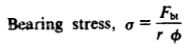
Characteristic strength of concrete and for a particular bar or group of bars in contact shall be taken as a centre-to-centre distance between bars or groups of bars perpendicular to the plane of the bend (mm); for a bar or group of bars  adjacent to the face of the member, a shall be taken as the cover plus size of bar.

78

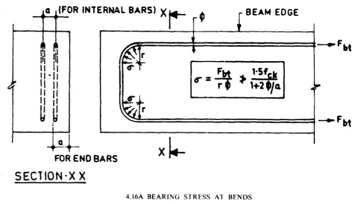
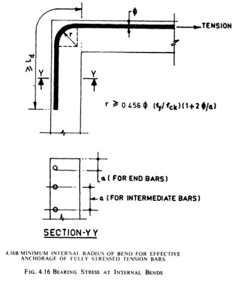
In other words, the minimum radius of the bend, r, should be such that 11

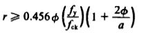
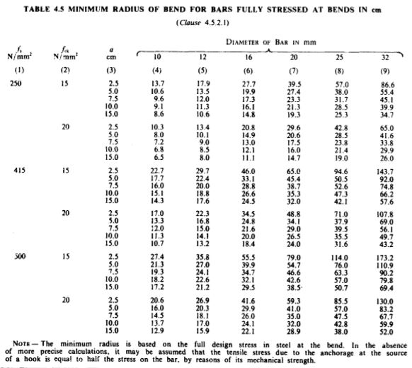
When the large steel stresses need to be developed il. ‘he bend, radial bearing stresses in the concrete may become excessive. The above equation controls the diameter of bend when there is a combination of high tensile stress in the bend. large bar diameter and low concrete strength. To simplify the application of the above formula minimum radius of bend is given in Table 4.5 for different grades of concrete and steel.

12.JPG

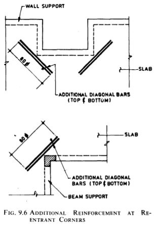
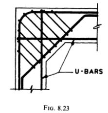
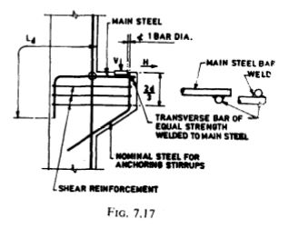
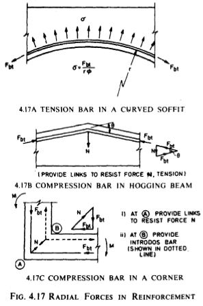
b) If a change in direction of tension or compression reinforcement induces a resultant force acting outward tending to split the concrete, such force should be taken up by additional links or stirrups. Accordingly in structural components with curved or angled soffits, or those formed with bends or corners, it should be ensured that the radial tensile forces due to changes in the direction of reinforcement are resisted by additional links (see Fig. 4.17). Bent tension bar at a re-entrant angle should be avoided.

13
c) The minimum straight length of hook is four times the bar diameter. For small diameter bars this should be a minimum of 5O’mm in order to facilitate holding the bar in place while forming the hook. The hooks when formed are quite large and while detailing it is important to ensure that they do not foul with other reinforcement, particularly where beams have more than one row of bars.

d) Reinforcing bars shall be so detailed that the hooks are not positioned in tensile zones of concrete as this may cause cracking. It is better to bend the bars so that the hooks and bars terminate in compression zones or so lengthen the bars to eliminate the need for hooks.

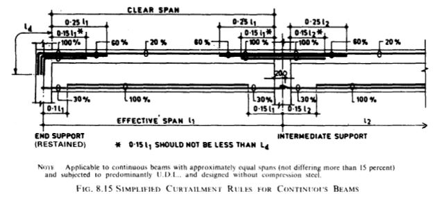
Curtailment of Tension Reinforcement in Flexural Members 

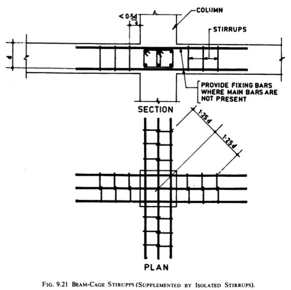
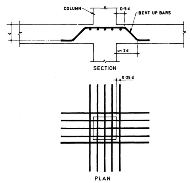
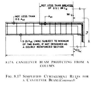
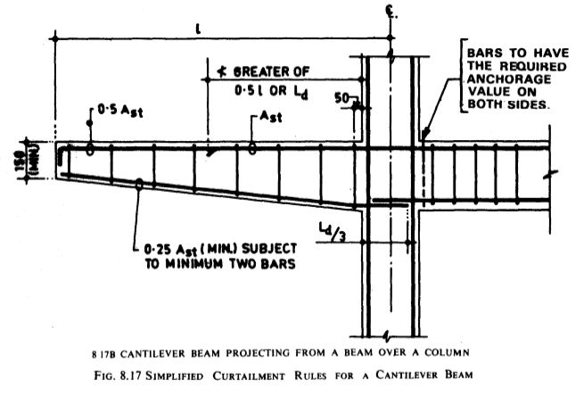
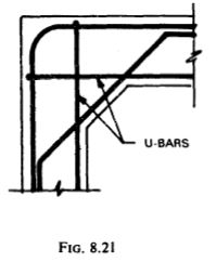
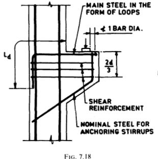
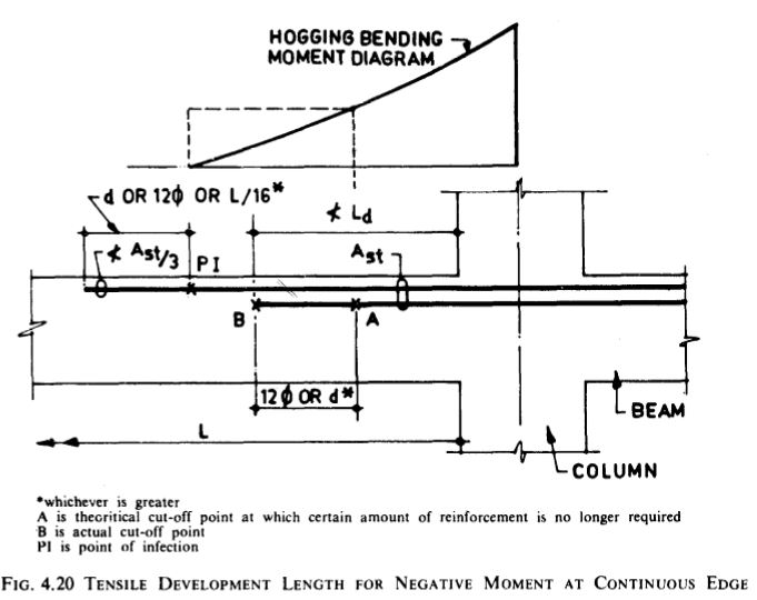
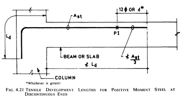
  • For curtailment, reinforcement shall extend beyond the point at which it is no longer required to resist flexure for,a distance equal to the effective depth of the member or 12 times the bar diameter, whichever is greater, except at simple support or end of cantilever. Figures 4.18 to 4.21 illustrate the requirement at cut-off point and at supports in flexural members.

Note 1 – A point at which reinforcement is no longer required to resist flexure is where the resistance moment of the section, considering only the continuing bars, is equal to the design moment.

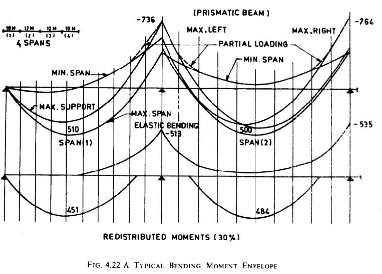
Note 2 -The points at which reinforcement can be curtailed is to be based\ on the bending moment envelope developed by the designer. It should be noted that the use of envelope helps in achieving better design. A typical bending moment envelope considering various loading conditions is given in Fig. 4.22.

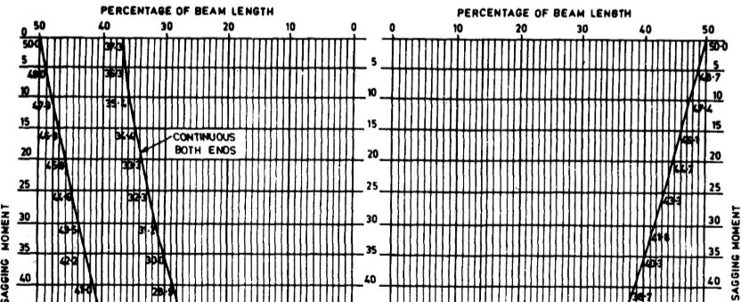
Figure 4.23 gives a standard bending moment diagram (based on uniformly distributed load) to enable designers to choose locations for curtailment of reinforcement. 

Flexural reinforcement shall not, preferably, be terminated in a tension zone unless any one of the following conditions is satisfied:

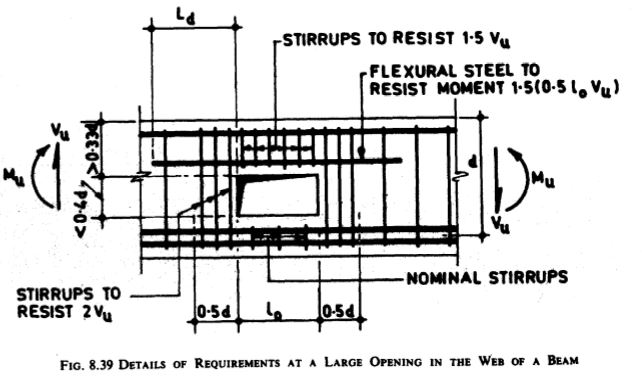
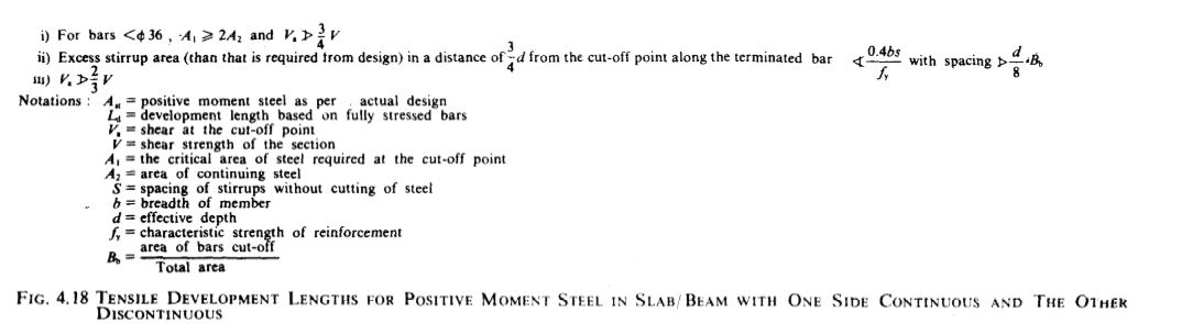
  1. The shear at the cut-off point does not exceed two-thirds that permitted, including the shear strength of web reinforcement provided.
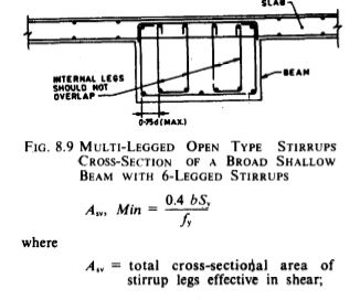
  2. Stirrup area in excess of that required for shear and torsion is provided along each terminated bar over a distance from the cut- off point equal to three-fourths the effective depth of the member. The excess stirrup area (sq.mm) shall be not less than 0.4 bs/fy, where b is the breadth of beam (mm), s is the spacing (mm) and fy is the characteristic strength of reinforcement (N/sq.mm). The resulting spacing shall not exceed (d/8)Bb , where Bb is the ratio of the area of bars cut-off to the total area of bars at the section and d is the effective depth.
  3. For 36 mm and smaller bars, the continuing bars provide double the area required for flexure at the cut-off point and the shear does not exceed three-fourths that permitted. 

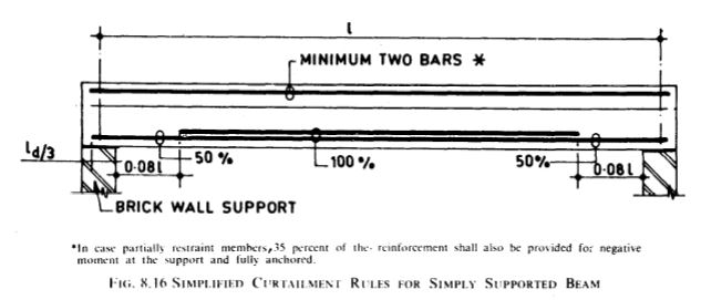
Positive Moment Reinforcement

a) At least one-third the maximum positive moment reinforcement in simple members and one-fourth the maximum positive moment reinforcement in continuous members shall extend along the same face of the member into the support, to a length equal to Ld/3 (see Fig. 4.18). where Ld is the development length based on fully stressed bars. This is required to provide for some shifting of the moment due to changes in the loading, settlement of supports, lateral loads and other causes.

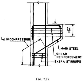
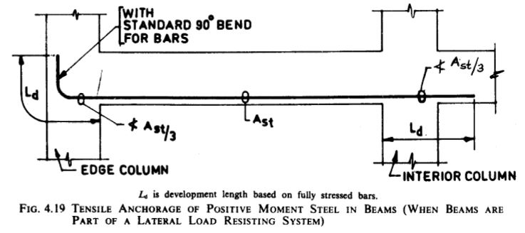
b) When a flexural member is part of a primary lateral load resisting system, the positive reinforcement required to be extended into the support according to (a) shall be anchored to develop its design stress (fully developed stress) in tension at the face of the support (see Fig. 4.19). This anchorage is to assure ductility of response in the event of unexpected over- stress such as from an earthquake. It is not sufficient to use more reinforcement at lower stresses. The full anchorage requirement does not apply to any excess reinforcement over and above that provided at the support.

At simple supports and at points of inflection, positive moment tension reinforcement shall be limited to a diameter such that Ld does not exceed (see Fig. 4.18)  14.JPG

17.JPG

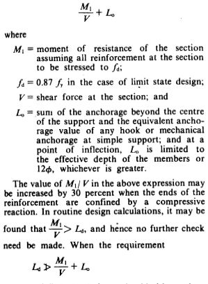
is not satisfied, the designer should either reduce the diameter of bars, whereby Ld is reduced, or increase the area of positive reinforcement at the section considered, whereby M1 is increased, or resort to botli the steps. 

1516

Negative Moment Reinforcement

At least one-third of the total tension reinforcement provided for negative moment at the support shall extend beyond the point of inflection (PI) not less than the effective depth of the member or 12 x diameter or one-sixteenth of the clear span, whichever is greater (see Fig. 4.20 and 4.21). 

181920.JPG21.JPG

2223

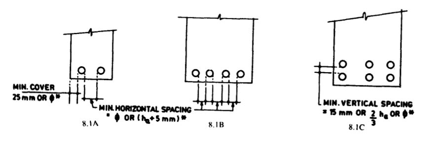
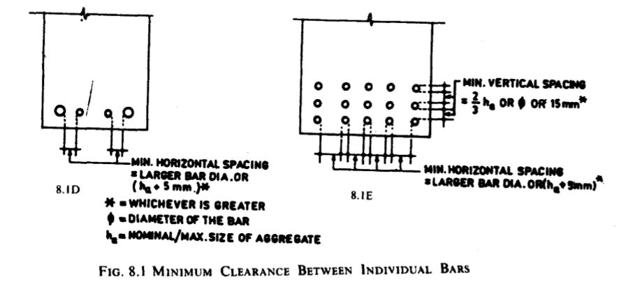
Spacing of Reinforcement

For the purpose of this clause, the diameter of a round bar shall be its nominal diameter, and in the case of bars which are not round or in the case of deformed bars or crimped bars, the diameter shall be taken as the diameter of a circle giving an equivalent effective area. Where spacing limitations and minimum concrete cover are based on bar diameter, a group of bars bundled in contact shall be treated as a single bar of diameter derived from the total equivalent area. 

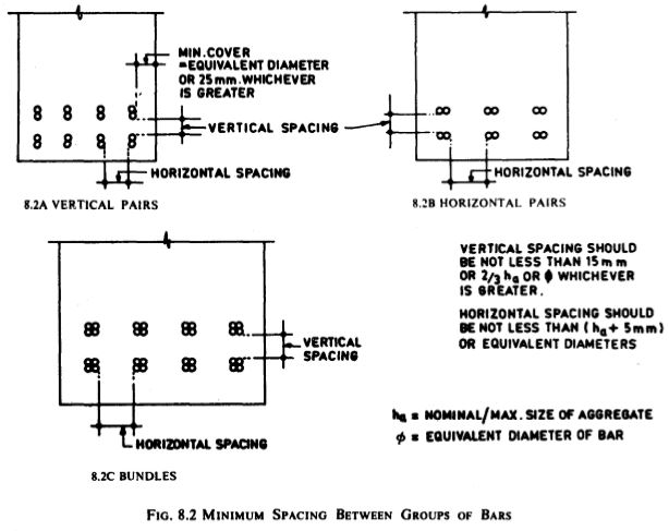
Bars Bundled in Contact 

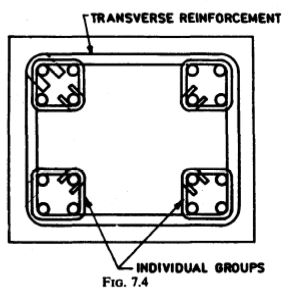
General – Bars in pairs, or in groups of 3 or 4 tied together and in contact side by side (bundled bars) may be used in beams and columns. This has been the practice in USA for many years, and is now permitted in most countries including India.

As bundled bars provide more reinforcement in less space than do single bars, it is possible to reinforce a member more heavily and still get better compaction of concrete. Beam and column sizes can thus often be reduced with saving in cost.

Bundled bars shall not be used in members without stirrups. Bundled bars shall be tied together to ensure the bars remain together as a bundle. Bars larger than 36 mm diameter shall not be bundled except in columns.

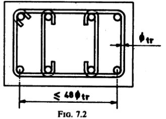
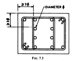
Whenever bar spacing limitations, minimum cover, tie size and spacing are based on bar diameter, a group of bars bundled in contact shall be treated as a single bar of diameter derived from the total equivalent area (see Table 4.6). However, the cover provided should be measured from the actual outside contour of the bundle.

Note 1- Unless patented splices are used, the bundling of bars in columns is not recommended, as all joints have to be staggered. However, even when patented splices are used the necessary staggering of splices makes assembly difficult and prefabrication cumbersome. 

Note 2- It is recommended to limit the bundle only to two bars or three bars as four bars many times do not tie into a stable bundle. 

Development Length

Ld of each bar of bundled bars shall be that for the individual bar, increased by IO percent for two bars in contact, 20 percent for three bars in contact and 33 percent for four bars in contact. The anchorages of the bars of a bundle can only be straight anchorages. 

Curtailment

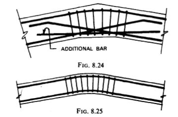
Bars in a bundle shall terminate at different points spaced apart by not less than 40 times the bar diameter except for bundles stopping at a support (see Fig. 4.24) 

Splicing

In case of bundled bars, lapped splices of bundled bars shall be made by splicing one bar at a time, such individual splices within a bundle shall be staggered. For bundles of 2, 3 or 4 bars, the staggering distance should be 1.2, 1.3 and 1.4 times the anchorage length of the individual bars respectively.

24.JPG


Structural Drawing for Detailing

Size of Drawing

  • The structural drawing a large project should generally be of one size, convenience both in the drawing office and on the site. The preferred sizes of drawing sheets are given in Table 3.1.
    Capture.JPG
  • The dimensions recommended for all margins and the divisions of drawing sheets into zones are given in Fig. 3.1 (A to F). 
  • The title block is an important feature in a drawing and should be placed at the bottom right-hand corner of the sheet, where it is readily seen when the prints are folded in the prescribed manner. The size of the title block recommended is 185 X 65 mm. 
  • Separate sheets should be used for each type of structural member or unit so that a floor slab would be detailed on one sheet, beams on another, and columns on a further sheet, etc. Alternatively, for small jobs each standard size sheet could be used to detail one floor of the structure so that the ground floor slab, beams and columns could be detailed on one sheet and the first floor members on another. 
  • Layout -There cannot be a single standard layout for the detailing of reinforced concrete drawings. However, practice to draw th hand corner of the I it is the usual (key) plan in the upper left eet, with the elevations and details below and on to the right side of the plan. Schedules and bending details are placed in the upper right corner of the drawing. Figure 3.2 gives a broad outline of layout recommended. In large projects, the bending schedule can be omitted from individual drawings and a separate bending schedule drawing may be prepared. 

Scale of Drawing 

  • Scales shall be so chosen as to bring out the details clearly and to keep the drawings within workable size. The choice of scale will depend at the discretion of the detailer/ designer and no general recommendations can be given in this respect. Some commonly used scales are given below as examples: 

1.JPG

Information to be Shown on Structural Drawings 

  • The overall sizes of the concrete members shall include the sizes of any necessary chamfers and fillets at corners. Also, the exact position, shape, size and spacing of the reinforcement within concrete members, as well as the required dimensions oi the concrete cover to the reinforcement shall be given. 
  • The position of any holes required in the members for service pipes and details of any pipes or other fixings to be cast-in with the concrete, and also, the position and details of construction joints and special recesses, etc. shall be indicated. 
  • When foundations or ground floor slabs are detailed, information regarding the underside conditions shall be shown, such as the use of waterproof paper, the thickness of blinding (the lean layer of concrete), if required. 
  • Notes should be used freely on detailed drawings. The most important being the ‘bar marks’ which give information about each, or a series of similar reinforcing bars. The notes should be concise and precise, and shall not be ambiguous. The notes which apply to the whole drawings, such as the specifications of the concrete to be used, size of chamfers and fillets, and concrete cover, etc, can be placed under a general heading at the bottom or side of the drawing. 
  • The beams, wall slabs, floor slabs and columns, etc, the main dimensions of the structure, such as the distances between columns, heights between floors, beam and column sizes, and floor and wall thicknesses, etc, as calculated by the design engineer shall also be shown on the drawings. 
  • Sections shall be drawn to at least twice the scale of plans or elevations to which they refer, while complicated joints such as may occur at the intersections of columns and beams may be detailed to larger scale, say I : 4. 
  • Structural drawings prepared by the designer shall show details of reinforcement and P all other information needed for detailing the reinforcement. The drawings shall also indicate, by separate notes, live loads, concrete strength, quality and grade of steel, number of bars to be lapped and lengths of the laps, and if necessary special instructions regarding erection of formwork, fabrication and placing of steel. 
  • It is convenient to detail the reinforcement by units which generally consist of footings, walls, columns, each floor and roof. A separate structural drawing supplemented by bar bending schedule should preferably be made for each unit. For small structures. the entire requirements may be handled as one unit. For a large project a particular unit such as floor may be divided to correspond with the construction schedule. 
  • To ensure that all the reinforcement is . properly placed or positioned in a unit, longitudinal section or cross-section should be shown in addition to plan and elevation of the unit on which the bars are shown. 
  • The drawing should be complete and clear so as to leave no doubt on any point of construction. Complete and accurate dimensions shall be shown. Clear and adequate details for special and unusual condition shall be given to ensure proper placing of reinforcement. Details of covers and intersections of walls. construction joints, window and door openings, and similar special features should be shown in the relevant drawings along with sketches, if necessary. 
  • For clear demarcation of reinforcement bars, those in the near face shall be shown in full lines and those that are placed in the far face shall be shown in dotted lines. 
  • All bars, straight or bent requiring hooks bends, shall be properly designated by the designer or a note to this effect included in the drawing. 
  • Lengths of laps, points of bend, cut-off points and extension of bars should be specified by the designer. The dimensions L/ 7, L/ 5 and L/4. etc. shown on typical drawings shall not be used unless justified by structural analysis. 
  • Wherever possible. all control and construction joints should he indicated on structural drawings and constructional details provided for such joints. 
  • Notes and instructions: Any ambiguity and scope for misinterpretation of instructions shall be avoided. All instructions shall be in imperative form, specific, brief and clear. 
  • Schedules -The reinforcement details of slabs, beams, columns and many other parts of structures may be effectively shown on working drawings in a tabular form, known as a schedule (see Section 5). 

1


2


3


4


5


6


7


8


Symbols and Abbreviations 

Symbols and abbreviations to be adopted in the drawings for reinforced concrete construction are given in 3.4.1 to 3.5.6. All reinforcement bars used in the structures shall be suitably designated and numbered both on drawing and schedule.

1


2


34


5


The symbols, abbreviations and notes shall be used in a manner that will not create any ambiguity. A few examples for representing diameter, spacing, number of bars,etc., are illustrated below: 

6.JPG


The use of the same type of line for the same purpose considerably enhances the clarity and usefulness of the drawing. The following graphical symbols are suggested:
7

8.JPG

9

Additional drawing conventions for use on drawings for reinforcement as suggested in IS0 : 3766-1977 ‘Building and civil engineering drawings-Symbols for concrete reinforcement’ is reproduced in Table 3.2. 123456

Marks for Parts of Buildings

  • Marks are used to designate the different structural members of a structure. Different structural members of a structure shall be marked using symbols, abbreviations and notations indicated in succeeding clauses and in the manner indicated in other clauses. 
  • A key framing plan shall be prepared to ai convenient scale and the two axes marked one side with alphabets A, B, C, etc. and the other with numbers (see Fig. 3.3). Normally with rectangular pattern, the same key framing plan may be used for all floors. However, if arrangement of beams vary for different floors a separate key framing plan with grid arrangement and areas may be used for each of the floor. The floors shall be .specified in accordance with the requirements of IS : 2332-1973 ‘Specifications for nomenclature of floors and storeys’ and abbreviations BT and MZ shall be used for basement and mezzanine, respectively, for example: 

7.JPG

  • Columns – Columns and foundations shall be specified by grid arrangement giving reference to the floor, for example (ie. 3.3A)

8

9

  • Beams, slabs and lintels, and tie beams shall be consecutively numbered from left-hand top corner (see Fig. 3.3A). 
  • If longitudinal section of the beam is shown, the grid of the column or number of the column supporting the beam is being detailed shall be as indicated as in fig. 3.3B and, if possible, inset on the drawing showing the key framing plan. On the other hand if a beam schedule is included, a table [see Fig. 3.3C] may be prepared and inset on the drawing showing the key framing plan [see Fig. 3.3A]. 
  • Beams or slabs that are similar may be given in the same number. 
  • Walls – Marking of walls shall be made in the serial order starting from top left corner of plan and proceeding towards the right, followed by subsequent rows in order. Longitudinal walls and cross-walls shall be marked separately (see Fig. 3.4) and identified in the drawing with reference to the serial number of the floor. 10.JPG

1


2


3


4

Bar Bending Schedule (Including Do’S and Dont’s in Detailing)

Bar bending schedules are very important out of detailing and should give the following information:

  1. Identification of the structural member(s), 
  2. Position of the bars in the structure,
  3. The bar mark,
  4. The diameter or size of bar,
  5. The number of bars of dne type in each structural member,
  6. The total number of bars of each type,
  7. The total straight length of the bar,
  8. The shape and bending dimensions of the bar,
  9. The details of bar chairs can also be included, and
  10. Remarks, if any. 

Schedules 

The reinforcement of slabs, beams and other parts of structures may be effectively shown on working drawings in a tabular form, known as a schedule. The schedule is a compact summary of the dimensions of the concerned structural part, all the bars complete with the number of pieces, shape and size, lengths and bending details from which fabrication details may be easily worked out. The dimensioning procedure for different bar shapes as shown in Tables 5.1 to 5.7 may be followed.
NOTE – The value of length is the length of straight bar from which the actual shape will be bent or for a straight bar, the length of that bar. This length will be equal-to the sum of individual overall lengths of the straight portions of each shape.

A schedule shall be supplemented with diagrams and sketches wherever necessary. Where bars of different dimensions are used, the exact arrangement of the reinforcement shall be shown by means of clear diagrams. No abbreviation or symbol shall be used in a schedule without proper explanation. 

For small structures detailed on a single sheet, the schedule may be placed in the upper left corner of the drawing. For larger structures requiring more than one drawing, the complete schedule may appear on the last sheet of the details, or if the size of the structure warrants,separate schedules may be prepared for each unit (foundation, abutments, piers, etc) on the drawing covering that specific unit of the structure. 

 Beams, Girders and Joists 

Details of reinforcement for beams, girders and joists are usually shown in schedules. The schedules should show the number, mark and location of member; number, size, position and length of straight bars; number, size, position, bending details and total length of bent bars and stirrups; size, shape and spacing of bar supports; and any other special information necessary for proper fabrication and placement of the reinforcement (see Table 5.8). Care shall be taken not to omit any controlling dimension such as overall length of the bar, height of the bent bar and location of bar with respect to supporting members where the bar is not placed symmetrically. The schedule should also include special notes on bending and any special information, such as the requirements of laps, two layers of steel, etc.

Slabs

The reinforcement for slabs is generally indicated on the plan, with details for the various types of bent bars shown in a schedule (see Table 5.8). The schedule shall be similar to that for bars in beams, except that the number of bars may also be obtained from the plan. Panels exactly alike shall be given an identifying mark or so specified in the schedule. 

In skewed panels, bars shall be fanned to maintain given spacing in the mid span. Additional bars for reinforcing the openings shall be as shown on plan.

In case of welded wire fabric sheet in slab panels, a schedule may also be included in the structural drawing indicating the mesh sizes (length and width) and fitting details for welded wire fabric sheets for different slab panels. A typical schedule is given in Table 5.9. 

Walls 

The reinforcement for walls shall be indicated on the plan, elevation and section with the details for various types of bent bars shown in schedule in a manner similar to that for beams and slabs.

Columns

The reinforcement for columns may be shown in a column schedule. Piles and pile caps should be treated as separate units and separate details or schedule or both may be provided. The main schedule may be supplemented with a smaller schedule for ties and by a small detailed sketch of each bar or type of bar with a table of dimensions. 

Schedule Layout

A typical form of schedule for beams, slabs and columns is shown in Table 5.8 and Table 5.9 shows another typical form schedule for slab using welded wire fabric as reinforcement. Also an example of typical bar bending schedule is given in Table 5.10.

International Standard IS0 : 4066- 1977 ‘Building and civil engineering drawings-Bar scheduling’ establishes a system of scheduling of reinforcing bars comprising the following aspects:

a) the method of Indicating dimensions;

b) a code system of bar shapes;

c) a list of preferred shapes; and

d) the bar schedule form.

This standard is reproduced in Appendix B as a supplement to the information contained in this section.

Do’s and Dont’s for Detailing

  • Do’s – General
  1. Prepare drawings properly and accurately. lf possible label each bar and show its shape for clarity.
  2. Prepare bar-bending schedule. if necessary.
  3. Indicate proper cover to reinforcement.
  4. Decide location of openings hole and supply adequate details for reinforcement around openings.
  5. Commonly available size of bars and spirals shall be used for reinforcement. For a single structural member the number of different sizes of reinforcement bar should be minimum.
  6. The grade of reinforcement bars shall be clearly mentioned in the structural drawing.
  7. For mild steel plain bars U-type, hooks and for deformed bars L-type hooks may be adopted. Deformed bars need not have hook at their ends.
  8. Bars shall have smooth curved edges at the point of bend.
  9. In case of bundled bars. lapped splice of bundled bars shall be made by splicing one bar at a time; such individual splices within a bundle shall be staggered.
  10. When reinforcement is left exposed for future construction, it should be adequately protected from corrosion and weathering action.
  11. Congestion of steel should be avoided at points where members intersect and make certain that all reinforcement shown can be properly placed.
  12. Make sure that hooked and bent bars can be placed and have adequate concrete protection.
  13. Make sure that bent bars are not so large and unwieldly that they cannot be transported.
  14. Indicate all expansion, contraction and construction joints on framing plans and provide details for such joints.
  15. Where a section is not on the same sheet as the plan from which it is taken, use a clearly defined system of cross-reference for locations of sections and details.
  16. Show enlarged details at corners, intersections of walls. beam and column joint, and at similar special situations. 
  • Do’s – Beams and Slabs 
  1. Where splices are provided in reinforcing bars, they shall be, as far as possible, away from the sections of maximum stress and shall be staggered.
  2. Where the depth of a beam exceeds 750 mm in case of beams without torsion and 450 mm with torsion, side face reinforcement shall be provided.
  3. In two-way slab, reinforcement parallel to the short span of the slab shall be placed in the bottom layer at mid-span and ih the top layer at support.
  4. All spacing shall be centre-to-centre spacing of bars.
  5. Deflection in slabs beams may be reduced by providing compression reinforcement.
  6. Only closed stirrups shall be used for transverse reinforcement for members subject to torsion and for members likely to be subjected to reversal of stress.
  7. At beam-column intersections ensure that the main beam bars avoid the main column bars.
  8. At beam-beam intersections, main reinforcement may be so arranged that layers in mutually perpendicular beams are at different levels.
  9. To accommodate bottom bars, it is good practice to make secondary beams shallower than main beams, at least by 50 mm.
  10. If it is required the beam cages may be pre- assembled with splice bars.
  • Do’s – Columns 
  1.  A reinforced column shall have at least six bars of longitudinal reinforcement for using in transverse helical reinforcement. 
  2. Spacing of longitudinal bars in column shall be along the periphery of the column. as far as practicable.
  3. Column bars of diameters larger than 36 mm in compression can be spliced with dowels at the footing with bars of smaller sizes and of necessary area.
  4. A dowel shall extend into a column, a distance equal to the development length of the column bar and into footing a distance equal to development length of the dowel.
  5. Keep outer dimensions of column constant, as far as possible, for re-use of forms.
  6. Preferably avoid use of two grades of vertical bars in the same element.
  • Dont’s-General
  1. Reinforcement shall not extend across an expansion joint and the break between the sections shall be complete. 
  2. Flexural reinforcement, preferably, shall not be terminated in a tension zone. If such case is essential, the condition as given in Section 4 shall be satisfied.
  3. Lap splices shall not be used for bars larger than 36 mm diameter except where welded.
  4. Bars larger than 36 mm diameter shall not be bundled.
  5. Where dowels are provided their diameter shall not exceed the diameter of the column bars by more than 3 mm.
  6. Where bent bars are provided, their contribution towards shear resistance shall not be more than half that of the total shear reinforcement.
  7. Different types of reinforcing bars such as deformed bars and plain bars and various grades like 415 N/sq.mm and 215 N/sq.mm should not be used side by side as this practice would lead to confusion at site. However, secondary reinforcement such as links ties and stirrups may be of mild steel throughout, even though the main steel may be of high strength deformed bars.
  8. Under no circumstances should the bending of bars at welds be permitted.


12


12


12


12


12


12


1.JPG


1


2


12


Detailing Functions

General

In preparing drawings and bending schedules, the following factors shall be kept in view:

a) The engineer’s design and the design requirements;

b) The cutting and bending of the reinforcement;

c) The placing and wiring in position of reinforcement; 

d) The maintaining of the position of reinforcement;

e) The pre-assembly of cages;

f) Concreting; 

g) The accommodation of other trades and services;

h) The measurement of quantities; and 

j) Economy in the use of steel. 


a) Design

The following requirements of the designer shall be borne in mind: 

1) The quantity, location and cover of steel reinforcement should be simply, correctly and clearly shown.

2) The placing drawings and bending schedules should be adequately cross-referenced, easily read and capable of easy checking in the drawing office and on site.

3) It should be possible to locate a detail readily, should a doubt arise. 

4) One detailer should be able to take over from another with a minimum of delay and direction. 

5) Detailing should be done in such a way that secondary stresses caused by support conditions, shrinkage, temperature variations, bursting effects of laps and splices, and stress concentrations arising from hooks and bends are counteracted.

b) Cutting and Bending

Prepare bending schedules on standard size sheets small enough to facilitate handling by clerical, fabrication and placing personnel.

Standardize cutting lengths and ensure that bending details are simple and easy to read. So compile the schedules that delivery of the required reinforcement for each component can be effected without the need for abstracting from schedules. The system of bar-referencing should be coherent and systematic, and should lend itself to easy identification and to use in computer systems, if necessary. 

c) Placing and Wiring in Position 

Ensure that drawings arc simple, pictorially clear, and adequately detailed to enable the fixer to place bars exactly where required. Avoid crowding drawings with information by detailing by components and also if necessary by preparing separate details for bottom and top steel in slabs. Ensure that reinforcing steel that connects elements to be cast at different times is so detailed that it is included with the portion to be cast first, for example, splice bars for columns, continuity reinforcing for beams and slabs to be cast in portions. If the order of casting is not clear, detail splices in one of the sections with suitable cross-references. Where the complexity of the detail is such that an, out of the ordinary sequence is required to place the reinforcement, ensure that such sequence is shown on the detail.

d) Maintaining Position of Reinforcement 

Reinforcement that has been placed and wired in position should not be displaced before or during the concreting operation. Ensure that bar supports and cover blocks are so scheduled or specified as to maintain correct bottom and side cover and that high chairs and stools are detailed to support upper reinforcement mats at the correct level.

e) Pre-assembly of Cages and Mats

Where required, so detail the reinforcement to components such as columns, foundations, beams, and walls that it can be conveniently pre-assembled before being placed in position. Ensure that assembled units are sturdy enough to stand up to handling and erection, and that they are not so heavy that they cannot be lifted by the men or equipment available for the work. 

f) Concreting

Ensure that the reinforcement can be spread as to follow placing and efficient consolidation of the concrete.

g) Other Trades and Services

Take note of the positions of down pipes (especially inlets and outlets), sleeves, pipes, and electrical conduits, whether shown on the structural layout or not. To avoid site difficulties, show them on the reinforcement details where necessary.

h) Measurement of Quantities

It is important that the quantity surveyor and the contractor should be able to compute the mass of steel used at any stage in a contract. Bending schedules prepared as recommended in 2.3 will assist in meeting this requirement. Ensure that placing drawings and bending schedules are adequately cross-referenced and that all revisions are suitably recorded. If. in the case of a revision, there is any possibility of doubt, prepare separate schedules showing only the revision, with adequate cross-referencing. 

i) Economy in Use of Steel 

The type of steel used is generally specified by the designer but
bear in mind that up to one-third of the mass of steel can be saved by using high tensile steel instead of mild steel. The saving can be considerable as the difference of cost between the rates for mild steel and high tensile steel placed in position is relatively small. Furthermore, as the rates for small diameters are higher than those for large diameters, it is desirable to use the largest available size of bar within the design requirements. Larger bars also. produce Stiffer cages and are not easily displaced.


Steel for Reinforcement

Reinforcing bars/ wires for concrete reinforcement shall be any of the following conforming to accepted standards: 

a) Mild steel and medium tensile steel bars

[IS : 432 (Part I)-1982 Specification for mild steel and medium tensile steel bars and hard-drawn steel wire for concrete reinforcement : Part I Mild steel and medium tensile steel bars (third revision)]. 

b) High strength deformed steel bars/ wires

[IS : 1786-1985 Specification for high strength deformed steel bars and wires for concrete reinforcement (third revision)]. 

c) Hard-drawn steel wire fabric

[IS : 1566-1982 Specification for hard-drawn steel wire fabric for concrete reinforcement (second revision)]. 


Mild steel and medium tensile steel bars

Grades of Steel

Mild steel bars shall be supplied in the following two grades:

a) mild steel bars, Grade I; and

b) mild steel bars, Grade II.


Tolerance

1) Bars in straight lengths 

a) The tolerance on diameter shall be as follows: 


2

b) The permissible ovality measured as the difference between the maximum and minimum diameter shall be 75 percent of the tolerance (k) specified on diameter. 

c) The tolerance on weight per m length shall be as follows: 3.JPG

2) Coiled bars

a) The tolerance on diameter shall be +/- O.5 mm for diameters up to and including 12 mm.

b) The difference between the maximum and minimum diameter at any cross-section shall not exceed 0.65 mm. 

14


High strength deformed steel bars/ wires

Grades of Steel

Deformed steel bars/ wires for use as reinforcement in concrete shall be in the following three grades:

a) Fe415,

b) Fe500, and

c) Fe550. 

Tolerance (High Strength Deformed Steel Bars)

Cutting tolerance on length

The cutting tolerances on length shall be as specified below:

a) When the specified length is not stated to be either a maximum or a minimum +75 mm or -25 mm

b) When the minimum length is specified+50 mm or – 0 mm 

Mass

For the purpose of checking the nominal mass, the density of steel shall be taken as 0.785 kg/sq.cm of the cross-sectional area per metre run.

Tolerances on nominal mass shall be as follows: 

5


Hard-drawn Steel Wire Fabric 

General

Hard-drawn steel wire fabric consists of longitudinal and transverse wires (at right angles to one another) joined by resistance spot welding. Fabrication of wire fabric by welding has the quality of factory fabrication and reduces cost of labor and fabrication in the field. 

Types

Hard-drawn steel wire fabric shall be made in the following two types:

a) square mesh, and

b) oblong mesh.

  1. The diameter of wires in the square mesh varies from 3 to 10 mm; the diameter being same in both longitudinal and transverse directions.
  2. In this case both longitudinal and transverse bars may serve as main reinforcement.
  3. The diameter of wire in the oblong mesh varies from 5 to 8 mm in the longitudinal direction and 4.2 to 6 mm in the transverse direction.
  4. The wires in the direction of larger diameter can serve as main reinforcement and the wires in the cross direction can serve as distribution steel. 
  5. The maximum width of wire fabric in rolls is 3.5 m; the length of this type of fabric is limited by the weight of rolls which may range from 100 to 500 kg.
  6. The maximum width of fabric in the form of sheets is 2.5 m and the maximum length is 9.0 m. The dimension of width is to be taken as centre-to-centre distance between outside longitudinal wires.
  7. The width of wires fabric in rolls or sheets shall be such as to fit in with the modular size of IO cm module and length in suitable intervals.

6

Tolerances

Tolerance on size of mesh

a) The number of spaces between the external wires in a sheet or roll shall be determined by the nominal pitch.

b) The centre-to-centre distance between two adjacent wires shall not vary by more than 7.5 percent from the nominal pitch.

c) The maximum variation in the size of any mesh shall be not more than 5 percent over or under the specified size, and the average mesh size shall be such that the total number of meshes contained in a sheet or roll is not less than that determined by the nominal pitch.

Tolerance on size of sheet

a) When fabric is required to be cut to specified dimensions, the tolerance shall be as follows: 

7.JPG

b) Tolerance on weight of fabric – The tolerance on the weight of fabric shall be as follows: 8


Detailing of Beam & Slab

PROBLEM No. 1

Draw the Longitudinal section and two cross sections one near the support and other near the mid span  of a R.C.C.  continuous beam with the following data:

Clear span of beams = 3 m each

Width of beam = 200 mm

Overall depth of beam = 300 mm

Width in intermediate supports = 200 mm

Main reinforcement = 4 Nos -12 mm diameter bars with 2 bars bent up

Anchor/hanger bars= 2-10 mm diameter

Stirrups = 6 mm diameter @ 300 mm c/c.

Materials : HYSD bars  and  M20 grade concrete

Picture2.jpg


PROBLEM No. 2

A rectangular beam of cross section 300 x 450 mm is supported on 4 columns which are equally spaced at 3 m c/c. The columns are of 300 mm x 300 mm in section. The reinforcement consists of 4 bars of a 6 mm diameter (+ve reinforcement) at mid span and 4 bars of 16 mm diameter at all supports (-ve reinforcement). Anchor bars consists of a 2-16 mm diameter. Stirrups are of 8 mm diameter 2 legged vertical at 200 c/c throughout. Grade of concrete is M20 and type of steel is Fe 415.

Draw longitudinal section and important cross sections.Picture3.png


PROBLEM No. 3

Draw to scale of 1:20 the Longitudinal section and two cross-section of a cantilever beam projecting 3.2 from a support using following data

Clear span  =3.2m

Overall depth at free end  = 150 mm

Overall depth at fixed end  = 450 mm

Width of cantilever beam  = 300 mm

Main steel = 4-28 mm dia with two bars curtailed at 1.5 m from support

Anchor bars  = 2 Nos. 16 mm dia

Nominal stirrups   = 6mm dia at 40 mm c/c

Bearing at fixed end   = 300 mm

Use M20 concrete and Fe 415 steelPicture4.jpg


PROBLEM No. 4

A cantilever beam with 3.2 m length is resting over a masonry wall and supporting a slab over it. Draw to a suitable scale Longitudinal section, two cross-sections and sectional plan with the following data:

Size of beam = 300 mm x 350 mm at free end and 300 mm x 450 mm at fixed end and in the wall up to a length of 4.8 m

Main steel: 4 nos. of 25 mm dia bars, two bars curtailed at 1.2 m from free end

Hanger bars: 2 nos. 16 mm.

Stirrups: 6 mm dia 2 legged stirrups @ 200 mm c/c the support length and @100 mm c/c from fixed end up to length of 1 m @ 150 mm c/c up to curtailed bars and remaining @ 200 c/c.

Use M20 concrete and Fe 415 steelPicture5.jpg


PROBLEM No. 5

A beam has following data

Clear span = 4m

Support width = 300mm

Size of web = 350 x 400

Size of flange = 1200 x 120mm

Main reinforcement  in two layers :  3-20 tor + 3-16 tor and to be curtailed at a distance 400 mm from inner face of support

Hanger bars: 3- 20 tor

Stirrups: 2L-8 tor @ 200 c/c

Use M20 concrete and Fe 415 steel

Draw longitudinal and cross section if the beam is

1.T-beam

2.Inverted T-beam

3.L-BeamPicture6.jpg


PROBLEM No. 6

Main positive reinforcement @ end span = 8 mm diameter @100 c/c

Main reinforcement in other interior panels = 8 mm diameter @ 200 c/c

Negative reinforcement @ all supports = 8mm diameter @ 200 c/c

Distribution steel= 8 mm diameter @ 200 c/cPicture7.png


Slab spanning in one direction (One-way slab)clip_image006.png


Slab spanning in two-directions (two-way slab)clip_image007.png